In bianco's picture, the LHS board is the ripple eater and the RHS board is the basic PSU board that comes with the kx-Amp board set (and the sx-Amp as well).
There are no ripple eater components on the actual kx-Amplifier module PCB's - its just the amplifier part.
If you want the ripple eater, you need to buy the PCB separately ($11.99 IIRC).
The ripple eater was designed after the kx-Amp and is designed to be used with any class A amp up to about 25-30Watts peak. please see the write up here for further info
Simple Ripple Eater PSU for the sx and kx-Amplifiers
(please note: I make no financial gain from any of these boards - I supply the PCB layout Gerbers to Jim's Audio and they do the rest. I just consider it a service to the DIY audio community from my side)
Last edited:
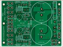
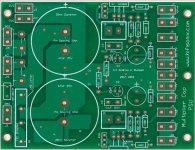
In bianco's picture, the LHS board is the ripple eater and the RHS board is the basic PSU board that comes with the kx-Amp board set (and the sx-Amp as well).
Seems the pictures on Jims are wrong - as I had suggested they could be - unless I'm missing something.
BTW, Hovering over the two pics (above) will confirm which is which picture.
I will print out tomorrow ripple eater and post details. Heh... yesterday I've put one 220ohm in trafos secondary before bridge, so previous measuring was bad.
Right now on my dummy load (5w parallel 330ohm resistors in water) i have on terminals:
Vneg-0 growing rapidly 75VAC (yes, AC), 35VDC
Vplus-0 stable 54VAC and 24.5VDC.
I promise to put tomorrow detailed measurement.
Maybe i should replace all transistors beforehand...
Right now on my dummy load (5w parallel 330ohm resistors in water) i have on terminals:
Vneg-0 growing rapidly 75VAC (yes, AC), 35VDC
Vplus-0 stable 54VAC and 24.5VDC.
I promise to put tomorrow detailed measurement.
Maybe i should replace all transistors beforehand...
No edit option... 21century... sorry for digression.
Im soo noob. I've soldered in two mje15033...
Now after correction i still have 70VAC on Vplus -0V terminals.
And proper 33VDC on both Vplus-0 and Vneg-0
I'd love to know if coil in series from one rect bridge leg to pcb can give lower DC as in formula lrc 0.9*vdc from bridge. I'll get more current maybe...
Just wondering whether I can substitute the NJW3281G/NJW1302G with 2SC3264/2SA1295 output transistors which are pin for pin replacements?
Reason being I have quite a few of them in my box trays and currently putting together my 'shopping list'.
Thanks
Have received the 2 ripple eaters from Jims (took about 1 month - impressive) and am awaiting the kx boards ordered around 1 week later.
Reason being I have quite a few of them in my box trays and currently putting together my 'shopping list'.
Thanks
Have received the 2 ripple eaters from Jims (took about 1 month - impressive) and am awaiting the kx boards ordered around 1 week later.
Just wondering whether I can substitute the NJW3281G/NJW1302G with 2SC3264/2SA1295 output transistors which are pin for pin replacements?
Reason being I have quite a few of them in my box trays and currently putting together my 'shopping list'.
Never mind, scrub the use of these output transistors as they won't fit the PCB if directly connected.
Also it seems the NJW are highly recommended.
Should have properly read the design notes first

I took a look at the Sanken devices- they look good and I would think they would work in this design.
But, the devil is of course in the detail, so there is no guarantee that there would not be be some OPS HF parasitic oscillation as these transistors are spec’d at 60 MHz fT which is double the devices specified in the design.
But, the devil is of course in the detail, so there is no guarantee that there would not be be some OPS HF parasitic oscillation as these transistors are spec’d at 60 MHz fT which is double the devices specified in the design.
Hi Bonsai,
Well I have a 0.4°C heat sink (300x100x40) that I use for testing amp boards before fitting into a chassis so maybe I could try this out with the 2SC/2SA output transistors and 'see what happens'.
I have a basic dual 60 MHz Instek 'scope but it might not be good enough. The Fourier maths is somewhat 'iffy'.
Attachments
(I’m originally from Durban BTW
Yellowwood Park & UND (Chem Hons)
CT for the last 23 years although I spent the last 15 years or so working outside SA in the ME and Africa
I have assembled a pair of Ripple Eater boards with which I intend to power my kx amp(one per channel). Using a transformer with 25-0-25 secondaries the r/e boards are outputting 36.7 vdc. Am I right in that I need to load the output with about 60R to simulate the 600ma current draw per channel or have I got my maths wrong? If someone would please confirm I would be grateful. tia.
For testing, you should load the ripple eater outputs.
I expect that the voltage will drop a few volts (will depend on transformer and caps you are using on the main supply).
At +- 35 V you must run the kx amp in class AAB mode - so the bias link on the board must be OPEN
I expect that the voltage will drop a few volts (will depend on transformer and caps you are using on the main supply).
At +- 35 V you must run the kx amp in class AAB mode - so the bias link on the board must be OPEN
- Home
- Amplifiers
- Solid State
- Hifisonix kx-Amplifier