The "Mid-Bias" setting ...
characterized by a value of 300 mV of voltage drop on the pair of output device emitter resistors R12+R13,
being more than the "Low-Bias" 200 mV,
but less than "High-Bias" 400 mV,
could be achieved by closing the J8 Bias connector with an additional 22k resistor.
Or in other words, "Mid-Bias can be achieved by R1 from 22k to a total of 44k.
Correct?
Or a grossly different value?
Last edited:
Why do you claim that 1000/35 is not suitable?Hi,
I intend to run Kx amp with 25vac=35vdc rails, and 1000/35 is not suitable. However 1000/50 with diameter 10mm is nowhere to be found. The best I can do is 470/50. Would that be usable in this case?
Thank
Did you ever try "reformatting" an electrolytic capacitor?
I suggest that you reformat the 35VDC capacitor into a 40VDC capacitor.
The series resistor for the reformatting process should be of a value that ensures that the maximum possible leakage current does not exceed twice the value of what is normally published by the manufacturer in the respective technical documentation for that capacitor. When the leakage current at 40VDC falls below the value as published to be normal by the manufacturer, then the capacitor is ready for use. This might take a few hours, or maybe a few days.
...
Now, putting aside the extremes as described in the paragraph aforementioned, the cap, if it is declared to be suited for 35V, then it probably IS suited for 35V. Specs for such capacitors have a certain safety margin and if the manufacturer is declaring it "good" for 35V, it will be actually designed to withstand some 5% more anyway.
It is not the voltage value that you should be worried about. Rather the ripple current that may be riding on this cap. Worth checking / verifying that the cap you intend to purchase and use for this function is of a high ripple current handling capability.
{Which should not be a problem or reason for concern in the specific place of the circuit, where these capacitors are to be used}.
Word of advice, in the context of the PSU board:
If you have a choice of two different makes of a 33000uF capacitor, diameter 35mm and various possible heights, for example 40mm, or 45mm or even 50mm, then choose the TALLEST one.
All other parameters being equal, you may notice in the specs that high ripple current handling capability is correlated with a big VOLUME of the cap. Volume as in cubic centimeters. The higher cap has a higher volume, so most probably has a higher ripple current handling capability.
Check the specs and compare.
And besides ... you can always use goggles. The worst thing that can happen is a big bang explosion, a lot of stink, some level of fumes, and a lot of confetti all over the place. Been there.
A reasonably conducted reformatting process, with verified decrease of leakage current to values below the published specs, is a good remedy to guard against such big bang. Would recommend reformatting of a new, "fresh from the factory" capacitor anyway.
Last edited:
In my KX, I actually used these ones, Panasonic FC. They have a diameter of 12mm. It is a tight fit, but actually possible to use.Hi,
I intend to run Kx amp with 25vac=35vdc rails, and 1000/35 is not suitable. However 1000/50 with diameter 10mm is nowhere to be found. The best I can do is 470/50. Would that be usable in this case?
Thank
[5szt] 1000uF 35V Panasonic FC kondensator Low Imp 7907067162 - Allegro.pl
I intend, or at least do not exclude the possibility, of using these KX boards at 35V in AB mode (from a dual voltage supply, with a toggle option). My heat sinks are specially over-sized for such a scenario.
I have failed in searching for a BoM for this amp (KX). The search function on this site is poor and Google takes me to an expired link. Can anyone supply a current BoM and post it here please?
I have AndrewT (R.I.P)'s NX amp and am really fond of it....the 'tell' is that the KX is perhaps even nicer for small-scale classical music and for Jazz. So I want to build it!
Many thanks.
I have AndrewT (R.I.P)'s NX amp and am really fond of it....the 'tell' is that the KX is perhaps even nicer for small-scale classical music and for Jazz. So I want to build it!
Many thanks.
I have failed in searching for a BoM for this amp (KX). The search function on this site is poor and Google takes me to an expired link. Can anyone supply a current BoM and post it here please?
Many thanks.
Here is all the KX info:
http://hifisonix.com/wordpress/wp-content/uploads/2018/11/kx-Amplifier-Oct-2018.pdf
You might want to look into a "Digikey BOM", as prepared / presented by our friend here, in post number #108.I have failed in searching for a BoM for this amp (KX). The search function on this site is poor and Google takes me to an expired link. Can anyone supply a current BoM and post it here please?
I have AndrewT (R.I.P)'s NX amp and am really fond of it....the 'tell' is that the KX is perhaps even nicer for small-scale classical music and for Jazz. So I want to build it!
Many thanks.
I hope that the "web basket" is still there and did not time out.
my project based on KX amp
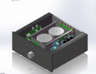
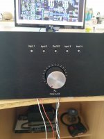
Hi guys. I would like to show my work on famous project "KX Amp" by Bonsai aka Mr.Russell,
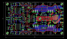
First picture show my amplifier, based on chassis made by Hifi2000, its a 4U chassis with black anonized coolers. Then I created a 4 input circuit, which is controlled by simple circuit and microswitches. Myself I redesigned the main PCB, which is dual layer and its designed to have fine rounded traces. And finally the design is dual mono, absolutly isolated two channels. Only the ground lifters or breakers are connected to the common safety ground.
All comments are welcome.
Hi guys. I would like to show my work on famous project "KX Amp" by Bonsai aka Mr.Russell,
First picture show my amplifier, based on chassis made by Hifi2000, its a 4U chassis with black anonized coolers. Then I created a 4 input circuit, which is controlled by simple circuit and microswitches. Myself I redesigned the main PCB, which is dual layer and its designed to have fine rounded traces. And finally the design is dual mono, absolutly isolated two channels. Only the ground lifters or breakers are connected to the common safety ground.
All comments are welcome.
Attachments
Last edited:
It was late last night / early this morning when I asked for a BoM. Clearly I was screen-blind!
Thank you all for pointing me in the right direction. I will report on progress. I am listening in the background to a Mozart violin sonata via an NX. With a KX added to my stock I may well enter into attempting a bi-amped system!
Thank you all for pointing me in the right direction. I will report on progress. I am listening in the background to a Mozart violin sonata via an NX. With a KX added to my stock I may well enter into attempting a bi-amped system!
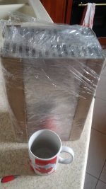
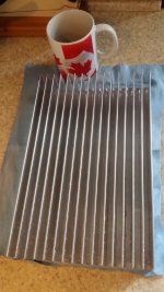
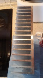
A 10kg parcel arrived today. Contents unpacked. Then went straight under a shower with strong jet stream of water. Needed to get rid of the filings, which were still between the fins. Dried up. The edges are nicely cut(*). I am very happy about how they prepared these. Four pieces of such profile: 30 cm long, 19 cm wide. The fins are 5 cm high.
I am considering making two separate monoblocks, bridged, in a "Tower Fashion", similar to a high PC enclosure. The length of the heat-sink determines height of Tower: 30 cm.
(*) They are normally NOT nicely cut. With less than perfect tolerances of 2mm.
But I asked them very very nicely, not to pack stuff off the ready goods shelf, but to prepare them separately for me. Will wait a few extra days. Asked to set the length to absolutely as precise as they can get it, set the cutting machine to slow forward go, and then to even out the edges. So they did. Better than I expected.
Radiator aluminiowy A6023 192x50x300mm Led-Byt.pl
... the exchange rate is roughly 4 zl into 1 USD.
Attachments
Last edited:
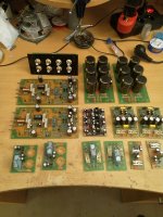
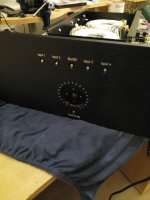
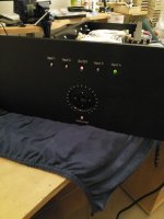
Top Secret Pictures ...Hi guys. Simple pictures taken during the work progress... Main PCB now on place, front panel showed....
")
uploading continue...
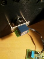
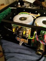
Hi guys. I will show more pictures....the "bowels" and detail to the potentiometer...i will replace them in the future by TKD CP2500 type potentiometer...but everything depends on money...
Hi guys. I will show more pictures....the "bowels" and detail to the potentiometer...i will replace them in the future by TKD CP2500 type potentiometer...but everything depends on money...
Attachments


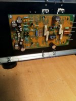
another step of assembling...
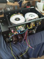
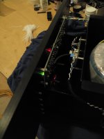
Hi guys, another pictures of assembling, the voltage stabilizers, input microswitches, A/AB switch are working/liting. The wiring to be done. Next step is assembly the amplifier PCB`s and speaker protectors...then the relay based input switch PCB...
Hi guys, another pictures of assembling, the voltage stabilizers, input microswitches, A/AB switch are working/liting. The wiring to be done. Next step is assembly the amplifier PCB`s and speaker protectors...then the relay based input switch PCB...
Attachments
Last edited:
- Home
- Amplifiers
- Solid State
- Hifisonix kx-Amplifier