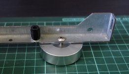
I spent some time filing the output transistors flat today (surface to heat sink), and the On transistors were actually more uneven then I expected.
This is a good thing to do to improve heat transfer from transistors, especially with high dissipation levels like class A. I read about it somewhere, sometime.. maybe Rod Elliott's pages, not sure.
Best done before the transistors are mounted, move the transistor on the file pressing it down with your finger.
I'm doing some 'therapy work' like this while waiting for the transformers. They should arrive next week. Heat sinks are painted, but I still need to finalize the chassis when I have all the parts so I can plan the layout.
I asked to have the transformers without resin in the middle, so I can add some turns myself in case I want to have a separate supply for the front end.
I have done some simulations with cap multiplier on the front end, and that does reduce the hum significantly. However it seems there is not much to be gained in output swing with increased front end voltage, saturation of the drivers and problematic clipping is the result. Just a few turns extra would be needed to compensate for the voltage drop in the cap multiplier.
Maybe just a separate (low drop rectifier maybe) PS for the front end would be an alternative too, not needing very large caps because of the low current needed for the front end, so basically no ripple.
Running a cap multiplier only on the front end could be problematic at start up since the front end supply come up slowly, but the output is powered instantly. I can't really see much difference in the sim, but still it makes me wonder.. Maybe some diodes would be needed to kick up the front end voltage from the 'power' supply. Thoughts/recommendations on that Andrew?
The reason for complicating things is that I would like to keep the supply impedance low to the output stage. Ripple eater increases it, at least in theory")
This is a good thing to do to improve heat transfer from transistors, especially with high dissipation levels like class A. I read about it somewhere, sometime.. maybe Rod Elliott's pages, not sure.
Best done before the transistors are mounted, move the transistor on the file pressing it down with your finger.
I'm doing some 'therapy work' like this while waiting for the transformers. They should arrive next week. Heat sinks are painted, but I still need to finalize the chassis when I have all the parts so I can plan the layout.
I asked to have the transformers without resin in the middle, so I can add some turns myself in case I want to have a separate supply for the front end.
I have done some simulations with cap multiplier on the front end, and that does reduce the hum significantly. However it seems there is not much to be gained in output swing with increased front end voltage, saturation of the drivers and problematic clipping is the result. Just a few turns extra would be needed to compensate for the voltage drop in the cap multiplier.
Maybe just a separate (low drop rectifier maybe) PS for the front end would be an alternative too, not needing very large caps because of the low current needed for the front end, so basically no ripple.
Running a cap multiplier only on the front end could be problematic at start up since the front end supply come up slowly, but the output is powered instantly. I can't really see much difference in the sim, but still it makes me wonder.. Maybe some diodes would be needed to kick up the front end voltage from the 'power' supply. Thoughts/recommendations on that Andrew?
The reason for complicating things is that I would like to keep the supply impedance low to the output stage. Ripple eater increases it, at least in theory

With a ripple eater you trade ripple reduction for output Z. Typical ripple attenuation is >30 dB, but more like 40 dB ( see scope shots on the ripple eater write up on hifisonix for example).
However, the output Z out the ripple eater is still very low, and amplifier feedback reduces it even further so that in practice, it’s a non- issue.
On the kx-Amp basic PSU, the AC Zout is 10-20 milli Ohms and with the ripple eater 50-100 milli Ohms. But, the PSRR on the kx-Amp is > 50 dB below 10 kHz.
The start-up/ switch off on the kx-Amp (and sx-Amp) is very well controlled. There is zero switch on/off thump and you don’t need speaker muting.
Until the front end comes up, the output stage is biased Off. Because the front end comes up slowly, and is controlling the overall loop and therefore DC offset, there aren’t any switch on/ off thumps
Last edited:
“ However, the output Z out the ripple eater is still very low, and amplifier feedback reduces it even further so that in practice, it’s a non- issue. “
Just reread this and I guess it’s confusing. What I meant to say was that the action of the amplifier feedback renders the slight increase in output impedance of the Ripple Eater essentially a non-issue.
Just reread this and I guess it’s confusing. What I meant to say was that the action of the amplifier feedback renders the slight increase in output impedance of the Ripple Eater essentially a non-issue.
I got it
I have some experiences with PS upgrades on other amps, and my ears tell me low impedance and big caps are good for bass control, so this means I go my own way again
My plan is to feed the output directly(linear PS), and make a separate shottky rectifier, smoothing caps and single transistor cap multiplier for the front end. Shottkys are to minimize voltage drop to compensate for the drop in the cap multipliers. If I find the voltage too low for the front end I will add a few turns on the transformers, but simulation indicates this should give slightly higher voltage than feeding the front end via the 33ohm resistors.
Rallyfinnen,
The output Zout of the kx-Amp is low. The action of the feedback is to lower the open loop Zout by the loop gain. On a sim at 20 kHz, the output Z is around 80 milli Ohms peak after the output coil. Your speaker cabling and internal speaker wires will probably be higher.
By all means use larger PSU caps since they will reduce the ripple at the expense of higher charging currents so watch out with your layout and keep wiring loop areas small as possible by twisting etc.
The same feedback action also applies to the PSU, which we state as Power Supply Rejection Ratio'. If the PSU impedance is say 100 milli Oms and you are drawing 1.2 Amp from it, that gives a ripple (over and above the smoothing cap ripple) of 120 milli volts. But the amplifier PSRR at 50 Hz is 55 dB to this gets reduced by about 400x referred to the input. For frequencies above 1kHz, the kx-Amp PSRR is >90 dB. A ripple eater improves this by at least 40 dB.
Last edited:
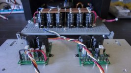
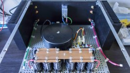
Still putting the final touches to the xK amplifier. The amps themselves have been mounted on the heatsinks on both sides of the chassis. Have had to find some bits of hardware for completion which has held it back somewhat.
The configuration thus far is:
1) Rear input switch with integrated fuse and RFI circuitry.
2) Power to DIYAudio soft start circuit and then to a 25-0-25V 500 VA transformer.
3) Transformer to dual fuse block (white)
4) Fuses to a pair of 40A bridge rectifiers and from their to 2 banks of 3 by 4,700 uF Caps per channel. Centre 'bus bar' is a virtual earth which will be connected to earth by one of the ripple eaters 'ground lift' circuits (I assume connecting both REs to earth would result in a 'ground loop' (?)
5) Inputs are the red and green wires (dual core screened) earthed to the chassis by 2.5N Polystyrene caps
2 ripple eaters are mounted on the front panel (10mm Aluminium).
My original thoughts were to use the cap banks to feed the ripple eaters and from the REs to the amps themselves via the REs bridge diodes.
The alternative would be to connect the fuses to the REs bridges (bypassing the chassis 35A ones) and from there to the cap banks and then to the xK amplifies.
Question arises as to:
1) Which would be the best topology from an electrical point of view.
2) Would the RE be able to handle the switch on current requirements in its output stage with an additional 14,100 uF across the output of each channel in addition to the xK Amp current on 'switch on'? (The input bridge rectifiers on the REs are 25A)
Additionally, the internal chassis plate is attached to the chassis frame by 12 mm plastic spacers (I think they are polyprop) except for the rear right one which is an 8 mm metal spacer with a 3mm S/S nut and lock washer which 'earths' the internal chassis base to the frame in that corner. Have not been able to source 12mm metal spacers and 10 mm is too small (internal thread length with available bolts - smallest countersunk I have is 8mm [Modushop chassis requires C/S head] and a 15 mm spacer makes the internal chassis base too high).
If I was to earth each corner of the internal base plate (using earth wires or obtaining 12mm metal spacers) would that also possibly cause earth loops?
Comments please?
Some pics attached.
Attachments
Rallyfinnen,
The output Zout of the kx-Amp is low. The action of the feedback is to lower the open loop Zout by the loop gain. On a sim at 20 kHz, the output Z is around 80 milli Ohms peak after the output coil. Your speaker cabling and internal speaker wires will probably be higher.
By all means use larger PSU caps since they will reduce the ripple at the expense of higher charging currents so watch out with your layout and keep wiring loop areas small as possible by twisting etc.
The same feedback action also applies to the PSU, which we state as Power Supply Rejection Ratio'. If the PSU impedance is say 100 milli Oms and you are drawing 1.2 Amp from it, that gives a ripple (over and above the smoothing cap ripple) of 120 milli volts. But the amplifier PSRR at 50 Hz is 55 dB to this gets reduced by about 400x referred to the input. For frequencies above 1kHz, the kx-Amp PSRR is >90 dB. A ripple eater improves this by at least 40 dB.
Yes, caps are actually larger per channel too, since I have one for each channel. But my point was that I want to try to skip the ripple eater for the outputs to keep the supply impedance low, and have a separate rectifier and simple ripple eater for the front end, which does seem to help the PSRR significantly in sim. It also isolates the front end from whatever other stuff the outputs might cause on the rails, which also makes me sleep better at night
As mentioned before, I was a bit unsure of the behavior at startup/shutdown with supply voltage delayed for the front end, but as I understood it, you think it should be ok.
Question arises as to:
1) Which would be the best topology from an electrical point of view.
2) Would the RE be able to handle the switch on current requirements in its output stage with an additional 14,100 uF across the output of each channel in addition to the xK Amp current on 'switch on'? (The input bridge rectifiers on the REs are 25A)
1. Because of my beliefs as mentioned above(low supply impedance), I would prefer the cap bank after the ripple eater.
2. I think the ripple eater should be fine like that, because it ramps up the voltage slowly, so the current 'should' not be a problem.
1. Because of my beliefs as mentioned above(low supply impedance), I would prefer the cap bank after the ripple eater.
2. I think the ripple eater should be fine like that, because it ramps up the voltage slowly, so the current 'should' not be a problem.
Thanks Rally,
Your previous comments are the ones that got me thinking of my PSU configuration.
BTW, I had 12 by 4,700 uF cap cans lying around which is why I put them in (A bit of 'bling' as well with the copper busbars for fun). Plus I could only get 10,000 uF Caps at 50 V (because of the 35V DC transformer voltage out), with the required 35 mm size, giving a total of 24,100 uF per dual power rail.
The 4K7 resistors across each cap bank in the photo are temporary to discharge the caps with the power off. Had some nasty surprises when the mains power was off but the caps still charged, even quite a few minutes later, when there was no power draw
Tony, can you make a quick sketch?
Hi Bonsai,
Knocked together a quick PSU flow diagram (attached) (I still draw stick people ...)
Hope this is sufficient.
Note that the 'Cap banks' are composed of 12 by 50V, 4,700uF caps I had lying around. 2 banks of 6 caps, 3 caps per rail. Common '0V' rail as per previous picture.
I used them because I couldn't get anything over 10,000 uf > 35V with the 35mm cap size on the RE boards, and the supply voltages are ±35V, so I opted for 50V, 10,000 uF (35mm) caps. I have since found 22,000 uF/50V with a 35 mm diameter but anything of higher capacitance at 50V or higher are generally 40 mm or larger diameter.
Anyway, would appreciate your comments on the attached options.
Thanks
Attachments
hi Bonsai I was able to fix the ugly jumper solution and now is better
Is possible to get the gerbers? I would like to build one.
Tony,
Either option will work ok. If you place the cap bank after the RE’s the PSU rather than before, the PSU output impedance will be lower. However, whether this will have any significance sonically, I cannot tell. As explained a bit earlier, the amplifier feedback works to effectively ‘lower’ the PSU output impedance and of course the amplifier open loop output impedance.
The cap bank charging currents will be quite high, so the RE dissipation can be high during power up.
You may want to consider using TO3P devices like those used in the kx-Amp OPS for the RE series pass devices. You can mount these on the heat sink - just keep the wires to and from the device to <150 mm and make sure they are twisted together.
Very nice looking build BTW - looking forward to the final pics !
- Home
- Amplifiers
- Solid State
- Hifisonix kx-Amplifier