I’ve tuned back in to this thread with all the new developments and troubleshooting you guys are performing.
Unfortunately, I abandoned this project because I couldn’t get the KX to behave properly. But, I still have the built boards unmolested. Hopefully there will be a plan developed for a re-birth!
Great work Fellas")
Unfortunately, I abandoned this project because I couldn’t get the KX to behave properly. But, I still have the built boards unmolested. Hopefully there will be a plan developed for a re-birth!
Great work Fellas
Tony/Rallyfinnen can you clip the scope probe earth to the scope probe tip and hold the loop near your scope screen. Please make sure the scope is at Max sensitivity (2mV to 10 mV per division).
What are you seeing?
Checked with my Instek 1062A scope @ 2mV and X1/X10 and there's only background noise.
Some additional info:
When 'cold' the oscillation is only around 1 mV but it 'bounces' up to more than double that and then reverts back to the 1 mV or so level. As the amp heats up the oscillation stays more stable but increases in value (I think my max was 80 mV RMS)
Touching C5 (10uF) also collapses the oscillation as does touching the 'grounded' pin (the track between Q3 and Q4) of Jumper J8
After ±5 minutes warm up R32/R33 get to 55°C (I have a contact temp probe). Found this increase in temperature whilst 'touching resistors'.
Just a comment based on other observations. My PCB is 'flat' on the heatsink. Distance from the base of the PCB to the heatsink is only around 5mm and would create a 'heat trap'.
Would this not have some consequences on stability being that close to a 'heat radiator'?
Finally a thanks to all those who are helping out on this project.
I'll do some 'fiddling' later today if I have the time.
But this amplifier is not brand new, it is years and years old. Nobody had a problem until last week? What has changed?
The kx-Amp was first published in 2018/19 and about 100 board sets have been sold. The sx and nx are much older (2011/2012).
Last edited:
Tony, once the amp settles after everything has reached temp equilibrium, the bias currents should be stable. They will drift around a bit as the amp warms up.
The instability issue we have encountered on some amps has to be completely solved as a separate issue - you should not have that under any conditions. My modules are mounted flat agains the heatsink which are positioned vertically - the power devices act as spacers at about 5 mm.
The instability issue we have encountered on some amps has to be completely solved as a separate issue - you should not have that under any conditions. My modules are mounted flat agains the heatsink which are positioned vertically - the power devices act as spacers at about 5 mm.
Tony/Rallyfinnen can you clip the scope probe earth to the scope probe tip and hold the loop near your scope screen. Please make sure the scope is at Max sensitivity (2mV to 10 mV per division).
What are you seeing?
I see only a straight line, not even noise.
Measurements
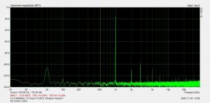
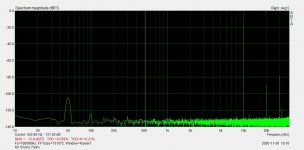
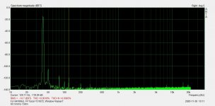
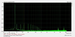
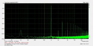
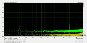
After adding a cap over R9, my hum went down a lot since IMHO any voltage over this resistor will be amplified by the amp. Hum reduction was even enough to make me try bypassing the ripple eater, and looking at the FFT, now I can hardly see any change in PSU noise on the output with or without it. This is of course running single channel (dual mono) setup.
I had some question marks before about distortion, and now I added 10x more damping to the input on the sound card just to rule out an overloaded input, but the result is the same. Increased amplitude gives a lot of harmonics, and it is independent of current (load), and gets worse with higher frequencies.
This is full Iq mode, no ripple eater.
Attachments
-
 KX 5Vrms 1k 7ohm.jpg90.3 KB · Views: 289
 -
 KX 5Vrms 10k 7ohm.jpg89.7 KB · Views: 289
 -
 KX 5Vrms 7ohm 40hz.jpg85.9 KB · Views: 276
 -
 KX 10Vrms 7ohm 40Hz.jpg88.7 KB · Views: 279
 -
 KX 10Vrms 7ohm 1k.jpg94.8 KB · Views: 284
 -
 KX 10Vrms 7ohm 10k.jpg90.9 KB · Views: 54
 -
 KX 10Vrms no load 10k.jpg91.1 KB · Views: 55
Last edited:
If your amp is prone to instability, that must be sorted first before doing anything else.
I will finish my tests later today and put the changes up. On.y after that can you address any other issues in your build.
R9 is a hum breaking resistor Rallyfinnen- it’s there to reduce cross channel ground loop currents. If you are getting hum with it in situ, please check for other noise sources but only after the above issue is fixed.
Last edited:
I did some probing around on my amp.
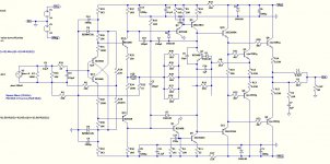
Strongest amplitude is on the emitter of Q10&11.
Then following it to the output bases:, all the bases of the outputs seem to have lower amplitude of oscillation. I guess this could mean that the drivers are driving the current into the bases of the outputs?
Putting my finger on the base of Q11 makes oscillation stop completely. Putting my finger on the base of Q10 only decreases the amplitude slightly.
I some stage of warming up, I could only see oscillation on the bases of the negative side outputs, and nothing on the positive side.
Could this have something to do with C2 on the positive side making it more stable, and no such cap on the negative side?
Maybe somebody could try the same to see if it's only my amp behaving like this?
BTW I tried to add some small caps parallel to C6 & C7, and that did absolutely nothing. (I only had two to test with)
Difficult to get one's finger on some PCB points. I find that touching the bases of Q10/Q11 with a small insulated screwdriver tip decreases the amplitude, or completely collapses the oscillation. Actually just touching the PCB itself (finger) close to the Q11 base diminishes the oscillation.
What I've found is that the oscillation is intermittent whilst the PCB/Heatsink is cold on startup but increases in amplitude as the heatsink temperature increases and the oscillation then becomes more 'permanent' as equilibrium is reached.
When still cold, touching various tranny contacts - and resistors - results in diminishing the oscillations.
When hot, many of the same components have no or little effect on the oscillation when touched.
My PCB is around 5 mm off the heat sink - and is currently lying 'flat' on my workbench, rather than horizontal - and will form a 'heat trap' between itself and the PCB. Even running in AAB mode the heatsink gets pretty damn hot. Not sure if this temperature is 'normal'. But because of the oscillation I don't run the amp for more than about 5 to 10 minutes to prevent possible damage to the components.
So here is a quick hack..
I took a RC based on what I had lying around: 150p & 1k5, and probed around a little bit. Adding it across R4 made oscillation silent on my board, and just for good measure I added the same over R5 too. It does not seem to affect the loop gain as far as I can see in my sim.
Maybe it has some other downside?
I hope Bonsai can examine this more in detail. I have now soldered them in and will see if it stays stable. So far so good..
If it works with no ill effects, it would be an easy and quick fix.
Attachments
Update:
I wanted to check if it was stable without zobel on the output (I would prefer if it was). At the same time I also removed the bypass caps for C1 & C6. Now I have oscillation at abt 16MHz 400mVp-p.
With the zobel + bypass caps, it was stable without any load resistor connected (and with load resistor).
Will experiment a little bit more.
- Home
- Amplifiers
- Solid State
- Hifisonix kx-Amplifier