I have not looked specifically at the output impedance of the ripple eater - I know that above a few Hz it’s very low. You should specify cap ESR to get a more realistic view. For a 1000 uF, 30-50 milli-Ohm is about right, and for the 47 mF 5-10 mili-Ohm. The ripple eater Zo is not as low as as the straight recitifier + reservoir cap. What it’s doing is filtering out the 100 Hz ripple (1.5 V pk - pk) down to about 15 mV.
At LF the amplifier PSRR is about 60 dB IIRC and the ripple eater > 30 dB (this is the input ripple from the filter caps) for a total of 90 dB.
The Zout is very low and under normal music signals, you can expect << 100 mV ripple. Large transients and clipping will increase this figure. The ripple eater Zo is not as good as a fully regulated supply - but that is much more complex of course.
For the Zo simulations and your plots, I would have to take another look but cannot do that until later this week.
Thank you for the reply. No need for you to put too much time into it. I just like to understand how it works, and if it can be made to work better with simple mods. It's kind of my thing to try to tune things, from engines to amplifiers ")
I will probably run the amp without ripple eater fist to listen and measure some more.
I will probably run the amp without ripple eater fist to listen and measure some more.
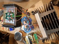
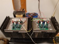
Made some progress with the build this weekend. Got some heat sinks from a friend. Was planning to use one for each channel, but my gut feeling told me I needed more, so I paired them up with two per channel.
I have done some 'heat tests' today and have no worries about the heat sinks. Case temp on the hottest output was abt 70deg C, and heat sinks around 40deg.
However transformer is abt 55deg C after abt 30min in high bias mode supplying both channels.. there is also some buzzing from the transformer under load, but I think it's tolerable.
I also checked the other similar Onkyo transformer I have, and core seems to be the same, but voltage is 20VAC on that one, and 22VAC on the one in the picture, so I donät think I can parallel them even with separate rectifiers. Not sure about the VA rating, but the marked power on the amp it was in is just over 500W. Here it will be asked to supply abt 200W continuous power, and that might be on the limit. I have some thoughts on adjusting the 'high bias' resistors to lower it a bit, and make it work with what I have. I rarely use more than a few watts when listening to music, so the the low bias mode would almost be enough for my needs. High bias seems to be almost 2A/channel.
I could also hear a fair bit of hum connecting a small speaker, but there is definitely a lot of pickup in that arrangement
DC offset seems stable, only varying a few mV. Current sharing between outputs is ok, but one pair has a diff of just over 10%, which I think is a bit much. Case temp is notably higher on the device carrying more current.
Attachments
Last edited:
The power transformer in a class A amp is critical because of the heavy constant load. Transformers for commercial class AB amps usually won’t cut it. These run with low constant load, and only have to provide high currents (over and above the reservoir cap charging currents) on high signal levels. For this reason, they usually won’t buzz when the amp is idling and only make mechanical noise at high volume levels. However, if you test with a load resistor at high power levels you often hear it. They are often run at high flux densities and with significant temperature rise even with low load to keep the cost down.
The transformer in my kx-amp is rated at 400VA, is double vacuum impregnated and cloth bound on a stabilized core (there’s a pri-sec screen and a GOSS band as well). The temperature rise after a few hours is about 10~15C above ambient.
So, an expensive item at about $80 in the UK but worth it.
Re the hum/noise, you obviously have big loops looking at the pictures eg DC from caps to module these need to be twisted together as well. Note also you will have very large EM fields off an EI transformer a d this could also be an issue.
Last edited:
I have tried another transformer now that seems to work. Windings get warm, but core stays cool. This is a really odd one, out of a Nixdorf computer from the 70's or possibly 80's I think it was made to run on constant high load.
I measured ripple loaded with both channels in high bias and 135mF caps, and it was 200mV p-p. It has a lot of secondary windings, so that has made me think of some alternatives.. (here we go again )
If I could feed the output stage with linear supply, and regulate the small signal part, since I have some extra windings to use. I could add 5VAC to each rail supply and rectify, and regulate that with LM317/337 to the small signal part. Maybe keeping it 1-2V above the rails of the output stage too? It would keep the supply impedance low in the bass, which think is nice. I have not simulated PSSR with this setup, what is your 'gut feeling' about this Andrew?
I think it was made to run on constant high load. I measured ripple loaded with both channels in high bias and 135mF caps, and it was 200mV p-p. It has a lot of secondary windings, so that has made me think of some alternatives.. (here we go again
)If I could feed the output stage with linear supply, and regulate the small signal part, since I have some extra windings to use. I could add 5VAC to each rail supply and rectify, and regulate that with LM317/337 to the small signal part. Maybe keeping it 1-2V above the rails of the output stage too? It would keep the supply impedance low in the bass, which think is nice. I have not simulated PSSR with this setup, what is your 'gut feeling' about this Andrew?
You can regulate the front end by replacing R15 and R17 (15 ohm resistors) with 1N4007 diodes and then taking the higher regulated supply to the small signal circuit side of the diode. Make sure your regulated higher rails are referenced to 0V and not just riding on top of the OPS supply rails as this will bring no PSRR benefit other than slightly higher output swing.
I have not tried boosted rails for the small signal section, so no guarantees from my side unfortunately.
A ripple eater will give the best improvement I think.
The PSRR on CFA’s is not as good as a decently designed VFA - just a trade off you have to live with unfortunately for improvements elsewhere.
Last edited:
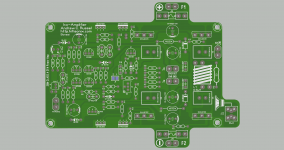
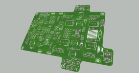
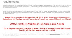
Hi Bonsai I'm doing a layout from the schematic and I want to know something here, this part of the PDF tells me that to run in class A the supply is @22-26V DC rails and J8 is pins are connected but if I want to chose class AAB then supply @35V DC rails and J8 pins are open I'm correct here? sorry for the silly question English is my second language and I sometimes need to be sure in things that I do when I read
Attachments
Last edited:
Some progress on this build again
Amps have been playing all day in the garage in low bias mode to keep PSU noise down. There is some noise with this setup, and also a minor constant oscillation visible on the scope, but it's just a temporary setup so far.
I did a quick distortion measurement with 7ohm load, but no distortion was visible above the PS induced harmonics around -80dB @ 1kHz (-60dB @50-150Hz area).
7+8k IMD seemed really clean, I think the best I have seen, with first harmonics around -80dB. Also multitone looked clean in the higher frequencies where PSU noise was lower. Promising!
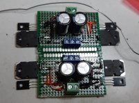
I went ahead and built two ripple eaters true DIY-style, using some beefier output transistors. Did a quick 'functional test' at 2A without any heat sink, and that was no problem. Transistors did not seem to heat at all.
I belong to those who think bass is improved with bigger PS caps, so I care about the impedance of the PS. I figured using double ripple eaters with bigger transistors should give the lowest possible supply impedance to the amps.
However I'm still thinking about the transformer and caps. A friend offered some beefy transformer he thought he had as left over, but could not find it, so I was back to what I have.
I was going to order the specified caps, but could not find more than one in stock when ordering other parts. Seems the european sellers normally don't stock these big snap in caps.
I do however have 4 new 33mF 50V caps, so I'm leaning toward double sets of rectifiers and caps using what I have. I have some basic PCB's for this too.
If the rest is double, I'm thinking it would be nice to double the transformers too.. I have the earlier mentioned Onkyo transformers with 22 & 20V secondaries..-I started thinking a Zener over each cap in the ripple eaters could limit the voltage to get equal voltages on both channels.
I have not simulated this, but I'm thinking my double ripple eaters with beefier transistors should cope with the extra dissipation if the voltage drop is sensible and cooling is ok.
I like dual mono, but on a budget
Comments are welcome!
Amps have been playing all day in the garage in low bias mode to keep PSU noise down. There is some noise with this setup, and also a minor constant oscillation visible on the scope, but it's just a temporary setup so far.
I did a quick distortion measurement with 7ohm load, but no distortion was visible above the PS induced harmonics around -80dB @ 1kHz (-60dB @50-150Hz area).
7+8k IMD seemed really clean, I think the best I have seen, with first harmonics around -80dB. Also multitone looked clean in the higher frequencies where PSU noise was lower. Promising!
I went ahead and built two ripple eaters true DIY-style, using some beefier output transistors. Did a quick 'functional test' at 2A without any heat sink, and that was no problem. Transistors did not seem to heat at all.
I belong to those who think bass is improved with bigger PS caps, so I care about the impedance of the PS. I figured using double ripple eaters with bigger transistors should give the lowest possible supply impedance to the amps.
However I'm still thinking about the transformer and caps. A friend offered some beefy transformer he thought he had as left over, but could not find it, so I was back to what I have.
I was going to order the specified caps, but could not find more than one in stock when ordering other parts. Seems the european sellers normally don't stock these big snap in caps.
I do however have 4 new 33mF 50V caps, so I'm leaning toward double sets of rectifiers and caps using what I have. I have some basic PCB's for this too.
If the rest is double, I'm thinking it would be nice to double the transformers too.. I have the earlier mentioned Onkyo transformers with 22 & 20V secondaries..-I started thinking a Zener over each cap in the ripple eaters could limit the voltage to get equal voltages on both channels.
I have not simulated this, but I'm thinking my double ripple eaters with beefier transistors should cope with the extra dissipation if the voltage drop is sensible and cooling is ok.
I like dual mono, but on a budget
Comments are welcome!
Attachments
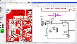
C4 is a non-polar electrolytic so it can go anyway around. I strongly suggest you stick with this. I’ll post up the Mouser part number
See here https://www.mouser.co.uk/Passive-Co...1yzvvqxZscv7Zgjdhub?P=1z0wrkiZ1yx4atvZ1z0yoh9
See here https://www.mouser.co.uk/Passive-Co...1yzvvqxZscv7Zgjdhub?P=1z0wrkiZ1yx4atvZ1z0yoh9
Last edited:
C4 is a non-polar electrolytic so it can go anyway around. I strongly suggest you stick with this. I’ll post up the Mouser part number
See here https://www.mouser.co.uk/Passive-Co...1yzvvqxZscv7Zgjdhub?P=1z0wrkiZ1yx4atvZ1z0yoh9
Hi Bonsai, please can you check if NTS650xx series transistors would be suitable for input when, 2 pnp or npn matched are required?
I wonder why no one use those.
Last edited:
- Home
- Amplifiers
- Solid State
- Hifisonix kx-Amplifier