Dear all,
Precis: there is hiss and crackle and no speaker output, but a very noisy headphone signal that improves to 'almost acceptable' (leaving a residual hum) after the units have been on for some time. Could it be simply that I need to replace all the capacitors in the amplifiers, or are there other transistor-specific problems I need to look out for?
For those unfamiliar with the system, the Z140 is a large combined power supply and power amplifier which uses DIN interconnects to supply power to the VG840 stereo amplifier and receive signals from it. In turn, the VG840 has a power connection for the EG740 stereo tuner and receives signals from it. The VG840 has tone, input select and a volume control.
I bought this stack mainly for the CR240 tape deck, which has another thread dedicated to it. However, I have been working my way through the Z140 and the VG840 as together they can be used as a useful system.
Inside both there are no obvious traces of heat damage or any unhealthy-looking capacitors. I have no ESR meter. I have cleaned all the contacts. The major transistors that I have tested give good readings. The relevant lights come on and no fuses blow. The DIN interconnects that I have made are not heating up or damaged.
Is it likely that I just need to methodically replace the electrolytic capacitors? I haven't done this before as I am inexperienced with full services of old transistor equipment.
I have circuit diagrams if it helps.
Sorted: having done rather more now, I realise the foolishness of replacing components willy-nilly. The capacitors are original and fine, there was just dirt and corrosion on the board-board connectors. Having methodically cleaned this off, I now just have a VG840 signal imbalance to track down, but any input through the VG840 plays happily through the Z140 or headphones.
I spent a long time looking for the reason why the +20V rail was up at 23V, thinking I had some SMPS fault to track down. It turned out the circuit was marked at 220V mains, so once I'd reduced our 240V down everything checked out.
An object lesson in being methodical!
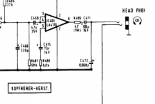
I've noticed the headphone output on the VG 840 has 63nF capacitors to ground after the 100µF coupling capacitors, but no resistors. I thought it was normal practice to load the output capacitors for when headphones are not inserted.
Is it worth my while to add resistors in parallel with the headphones, or did the designers have a good reason for doing it the way they did?
An object lesson in being methodical!
I've noticed the headphone output on the VG 840 has 63nF capacitors to ground after the 100µF coupling capacitors, but no resistors. I thought it was normal practice to load the output capacitors for when headphones are not inserted.
Is it worth my while to add resistors in parallel with the headphones, or did the designers have a good reason for doing it the way they did?
Attachments
Last edited:
- Status
- This old topic is closed. If you want to reopen this topic, contact a moderator using the "Report Post" button.