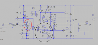
Attached is the schematic of our old family quasi amp.
The values are taken from an original factory schematic and may be different than actually installed.
I'm not an EE but I can tell it's a modified implementation of the RCA design.
After reading many threads and looking at so many schematics I can tell there are some aspects of the schematic that are different from the norm.
My first question relates to the modified Self beta enhanced EF vas.
What is the purpose of the diode in parallel with the Miller cap?
What is the purpose of the cap between the collectors of the first and second vas transistors? Can this be altered/removed? Is it going to provoke oscillations?
Secondly,the feedback circuit looks funky to me with two caps and two resistors. All suggestions and comments welcome.
Cheers
p.s. the amp actually sounds remarkably fine right now
Attachments
Last edited:
When the Darlington Q6 Q7 saturates it is slow to recover. D4 clamps drive to Q6 when Q7 is near saturation, recovery is quicker.
The feedback network sets the AC impedance to Q2 Base to about 99 Ohms, but sets the DC impedance to 10K, to mirror the 10K at Q1 Base.
FWIW, C3 C2 are "reverse bias". Because the DC voltage is maybe 0.5V, this should not harm the caps. However I wonder if your drawing is different from the actual build. (If you are sure, I accept that this 'error' might well have been overlooked even into production and family use.)
The compensation scheme caps.... life is too short to figure-out funky old amps. I am struck by C8 and that whole voltage-divider, when a complementary sequence could have direct-coupled.
Hey, wait: it is a push-pull Vas. Q9 mirrors current. R16 R18 waste-off high voltage. I do not recall any such thing as an "RCA" plan. (Basically Jack left before device prices came down enough to encourage such fancy designs.)
If it is working "remarkably fine right now", leave it alone.
Leach also used the two resistor trick in his super leach amps published at the Audio magazine in 1980..
the ltp input to the left hand to ground is made equal to the ltp right hand input at dc to virtual output node also a ground in ac terms...
so that the two resistors work at ac only using the ecap to couple feedback to the input ltp...
the ltp input to the left hand to ground is made equal to the ltp right hand input at dc to virtual output node also a ground in ac terms...
so that the two resistors work at ac only using the ecap to couple feedback to the input ltp...
C10,C12
Feed forward high frequency compensation.
Thanks for the reply.
Does the LTP CCS with D1,D2 look unusual? I haven't seen this arrangement before.
- Status
- This old topic is closed. If you want to reopen this topic, contact a moderator using the "Report Post" button.
- Home
- Amplifiers
- Solid State
- Variation of beta enhanced vas and other weirdness