MMCF10 amp HIFI LP phonograph MM amplifier RIAA Phono preamplifier PCB Board | eBay
Have anyone tried this one?
Have anyone tried this one?
Phono preamp
I bought the board you describe but have not built it yet. It confused me because it has two stages of voltage regulation which is beyond my understanding.
However, I have built the yellow colored board (current Ebay number 292448115622) that uses one OPA 2604. This IC is discontinued but available from Juried engineering on Ebay. It really sounds good. Great resolution. Enough gain. Soft on the high end right now probably due to my using $3 Panasonic coupling capacitors and a simple Ebay kit power supply. I used Dale resistors and Wima capacitors. If you are looking for a sonic bargain, I would recommend this one.
My reference phono stage is a Pass DIY Pearl II that I built two years ago (lowered gain). It is a very good preamp project but at a difference price point. I use an Ortofon 2M Black cartridge and an Ebay board headphone amp which uses LM49600 buffers (also a bargain I recommend). I still listen with 25 year old Grado SR60 headphones.
> confused me because it has two stages of voltage regulation which is beyond my understanding.
I live out in the woods. I can easily buy rough boards cut right from the tree. I have three in my shed, and one as a kitchen counter-top. They are tapered and bumpy. This is like raw wall-power: raw stuff, but needs to be cleaned-up for nice projects.
Say I was building a bench with a nice 15" wide seat. I get a wider rough board and cut it to 15". However cutting rough wood is rough work, doesn't go through the saw smoothly, and it likely won't be perfectly right. Instead I might cut it a little wider as a first pass, then make my final 15" cut as a second pass.
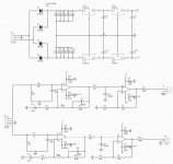
This board takes raw +/-24V DC from wall-power, cuts it to +/-18V DC. But a phono preamp could be real sensitive, you want really clean power. So they added a second stage to shave 18V down to 15V. After double-regulation, the final DC should be really smooth.
Depending on implementation. If the rectifier loop couples through the layout to the regulator "ground", buzz can be injected that the regulator won't cancel. You can't usually get any clue from eBay or Amazon pictures.
I live out in the woods. I can easily buy rough boards cut right from the tree. I have three in my shed, and one as a kitchen counter-top. They are tapered and bumpy. This is like raw wall-power: raw stuff, but needs to be cleaned-up for nice projects.
Say I was building a bench with a nice 15" wide seat. I get a wider rough board and cut it to 15". However cutting rough wood is rough work, doesn't go through the saw smoothly, and it likely won't be perfectly right. Instead I might cut it a little wider as a first pass, then make my final 15" cut as a second pass.
This board takes raw +/-24V DC from wall-power, cuts it to +/-18V DC. But a phono preamp could be real sensitive, you want really clean power. So they added a second stage to shave 18V down to 15V. After double-regulation, the final DC should be really smooth.
Depending on implementation. If the rectifier loop couples through the layout to the regulator "ground", buzz can be injected that the regulator won't cancel. You can't usually get any clue from eBay or Amazon pictures.
mine cuts -+ 32volts to +-22v (HA1457) then to +18 for the single transistor input stage. I know there are better, but specs are excellent as is the scope output at 20khz. THD < .005% as tested in the RIAA circuit.
no 60 or 120 Hz ripple whatsoever. It appears to be a good design.
no 60 or 120 Hz ripple whatsoever. It appears to be a good design.
Last edited:
I have built one of these up out of curiosity using fairly good quality components, R core transformer etc. The audio quality is excellent and surpasses the Rega fono etc with one exception.... at higher volume levels there is a discernable hum... Looking at the board layout the regulator ground is connected to the audio ground at the star point and the op amps connected this way also.
Let me guess: The amp is built with a GND to PE connection, and there is another somewhere in the system, prompting a ground loop? Or none of all this maybe? The turntable ground wire is connected?I have built one of these up out of curiosity using fairly good quality components, R core transformer etc. The audio quality is excellent and surpasses the Rega fono etc with one exception.... at higher volume levels there is a discernable hum...
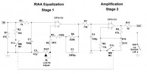
The schematic...
indicates an amplifier quite similar the one discussed in this thread, so I assume it may be based on the same JLH concept. Sure looks similar to the K1500 JLH pre (the first variety with some actually sensible MM/MC switching I've seen, possibly owing to it being newer).
Attachments
I have had another look at this. The hum was coming from the left input, which came and went as a touched the connecter. I replaced the RCA chassis input and it disappeared.
There is a similar build here DIY MMCF10 Phono Preamplifier - Album on Imgur (not mine), with mine I built the R core transformer into a seperate box and took the -/+ 35 v AC out to the phono amp so there is no direct connection to the mains supply safety earth.
In response to mixi's question - I liked the simplicity of this design especially the multiple stage regulators in the PSU and the noise rejection this brings in a very acceptable price point - especially considering I need to build three.
The end result is excellent and performance exceeds the much more expensive commercial phono amps I have.
Trying to revive this thread, if someone is interested.
There's another thread on this forum, dealing with BJT and FET RIAA preamps, that might be interesting reading for those interested.
FET vs BJT input phono preamp
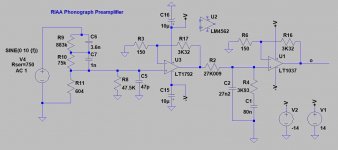
The actual schematic for the MMCF10 preamp is not the one shown above, but this one here. I got it from the seller.
But that project has some issues that come out if you simulate it in LTSpice as I did. OTOS the kit you can get from several sellers is handy, as first of all you have a pcb, that you would need for a similar project.
My proposal is to use the pcb and some of the passive parts, IC sockets, connectors, to assemble a preamp like that I enclosed.
ZEROZONE MMCF10 Hifi LP Phonograph MM Amplifier Kit / RIAA Phono Preamplifier Kit DIY|preamplifier kit diy|phono preamplifier kitpreamplifier kits - AliExpress
So first of all, those that might be interested please show yourselves and speak up.
There's another thread on this forum, dealing with BJT and FET RIAA preamps, that might be interesting reading for those interested.
FET vs BJT input phono preamp
The actual schematic for the MMCF10 preamp is not the one shown above, but this one here. I got it from the seller.
But that project has some issues that come out if you simulate it in LTSpice as I did. OTOS the kit you can get from several sellers is handy, as first of all you have a pcb, that you would need for a similar project.
My proposal is to use the pcb and some of the passive parts, IC sockets, connectors, to assemble a preamp like that I enclosed.
ZEROZONE MMCF10 Hifi LP Phonograph MM Amplifier Kit / RIAA Phono Preamplifier Kit DIY|preamplifier kit diy|phono preamplifier kitpreamplifier kits - AliExpress
So first of all, those that might be interested please show yourselves and speak up.
Attachments
My wife is pressing me to put the turntable to work again, or she will buy an "LP destroyer" turntable they sell over here to play our LPs. Which would actually destroy the discs.
So I have to start one of both phono-pres I want to assemble quite soon. One thing to decide is what supply to use: an LM3X7 + Denoizator or a Superregulator. The problem is that both supplies demand using two separate supplies for each channel, something none of ready-kits I bought come with.
So I have to start one of both phono-pres I want to assemble quite soon. One thing to decide is what supply to use: an LM3X7 + Denoizator or a Superregulator. The problem is that both supplies demand using two separate supplies for each channel, something none of ready-kits I bought come with.
- Home
- Source & Line
- Analogue Source
- PCB for phonoamp