Dear Friends,
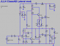
I enclose the original circuit of JLLH-20 watt Class AB circuit as published in WW-7-70. I built this circuit, a single channel long ago, in early 80s.
Recently, my interest was revived in this circuit. I made a circuit using Lateral Mosfets in LT spice and it is enclosed. I made some minor (I hope) additions and changes.
I require help in properly evaluating this circuit for Distortion and FFT, Square wave response, Stability (Tian probe) and overload behavior. If separate ascs are provided for each test, it will help me and others also as a learning exercise.
--gannaji
Attachments
Dear bogdan,With latheral ops, you could try to remove the driver stage (Q3), no need for it.
How do we ensure that! Please help in properly simming the above circuit !
--gannaji
Dear Bimo,
Thank you very much for responding and coming to my help. I also thank you again for doing a similar exercise for the Retro TGM8. Actually I tried to copy paste the spice directives etc into this diagram but without success. My difficulties are as follows:
--gannaji
Thank you very much for responding and coming to my help. I also thank you again for doing a similar exercise for the Retro TGM8. Actually I tried to copy paste the spice directives etc into this diagram but without success. My difficulties are as follows:
- I included "my models.txt" in the upload. It contains models of transistors I am having. They are a selective copy paste from cordells models only. Kindly use those transistors and those models. Or please include your copy of models.
- Your main change seems to be C8 and C7 for stabilization instead of single C8. Thank you for this.
- Your .asc file is actually FOUR separate simulations put in one file. Some amount of disconnect-connect exercise is required to run each simulation. Can you kindly post them as four or more .asc files, with each file corresponding to one type of simulation only ?
- I am also particularly interested in the way JLLH implemented the EF buffer. But not clear how to connect the Tian probe etc. I will be obliged if you can kindly use the .asc file I posted, with any obvious mistakes corrected, for further simulation of stability with Tian probe !
--gannaji
My trials to simulate
Dear Bimo,
Today, I took your .asc file, 'duplicate-paste' my original circuit into it and tried simulation. This file is uploaded.
gannaji
Dear Bimo,
Today, I took your .asc file, 'duplicate-paste' my original circuit into it and tried simulation. This file is uploaded.
- DC simulation is ok.
- Tried AC simulation - ok.
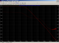
- Tried Tian probe simulation. .ASC file and Result files are uploaded. The gain of the circuit seem to be <40db. Kindly comment on the other points.
- Tried Transient simulation. Did not run. Objection about 1N4004C. Removed it. Now it Exits saying 'Singular Matrix". What is wrong?
gannaji
Attachments
Sorry, I'm using micro cap, ltspice is too comlicated...Dear bogdan,
How do we ensure that! Please help in properly simming the above circuit !
--gannaji
I make this as simple as possible. But you can add buffer before latfet to improve it.
To improve what, distortion? If you want low distortion, you would't make jlh69, so it doesn't says a lot... Better make it and listen.
")
Dear Bimo,
Today, I took your .asc file, 'duplicate-paste' my original circuit into it and tried simulation. This file is uploaded.
Kindly help.
- DC simulation is ok.
- Tried AC simulation - ok.
- Tried Tian probe simulation. .ASC file and Result files are uploaded. The gain of the circuit seem to be <40db. Kindly comment on the other points.
- Tried Transient simulation. Did not run. Objection about 1N4004C. Removed it. Now it Exits saying 'Singular Matrix". What is wrong?
gannaji
You get voltage gain by drawing current through a load attached to the collector in a common emitter stage. From Ohms law the more the current the greater will be the voltage drop available to drive the next stage.
The main voltage amplifier is Q3 and seeing that Q4 runs in Class A Linsley-Hood added a collector resistor to this to augment the loop gain - R23 at 47R.
There are a couple of obstructions to the flow of collector current since the carrier charges originate from the emitter and flow to the collector. In the case of Q3 this is R39 at 10R and with Q4 a series combination of R30 at 1k and R31 at 2.2k.
The differences between this circuit and the original JLH account for the results you are seeing.
To run the other simulations you have to connect a line between the signal and the input. Conveniently the commands are adjacent to the symbols.
Multi purpose simulations don't suit everyone - I suggest you create copy the Tian simulation and from this create separate files for each of the other signal tests and in these delete the .commands that do not apply.
- Status
- This old topic is closed. If you want to reopen this topic, contact a moderator using the "Report Post" button.
- Home
- Amplifiers
- Solid State
- JLLH 20watt Class AB Lateral Mod