Hello everybody,
I could buy a rotel 840 BX4, I was curious to hear a Rotel from the glory years of the brand. It's a pretty good amp ! I was afraid of finding a tonal balance more on the trebbles, with a sound very detailed but on the harsh side. And in fact I found it well balanced, with deep bass (I have a Quad 405 recaped, it's a really a "lighter" sound) and a lot of air between the instruments...
I bought it in a good condition, but very dirty, the last owners didn't take very care of it. When I tested it, back to home, I loved the sound, but I found it pretty hot, too. I could hear that these amps are running in class A the first 5 watts, it can be an explanation, but I wasn't sure of that...
So, I read plendy of posts on diyaudio, and I realized that : " To adjust a bias on a Rotel Amplifier ? Nothing more simple !
") "
"
I had between 9 and 10 mV before on the 0,22 ohm resistors, now I have my 2,5 mV. And I had 41 mV, and 74mV DC on the speakers output, this is past now. I can't hear any difference on the sound. Shall I ? Perhaps a sound a very little more... Dynamic, I'm not sure. But I find it a little colder when working now. So, thank you diyaudio !
Perhaps 2 or 3 questions ?
- Is it right that these amplifiers works in A class for the first 5 watts ?
- I did my adjusments with a 3 digits multimeter, on the 200mV range. Not a professionnal gear... What can happen if I adjust a too low voltage on the 0,22 resistors ?
- I suppose I'll need soon to recap it, it was made in 1990-1991, nearly 30 years.. Does it make sense to put 2 bigger capacitors (from 8200uF to 12.000) in the PSU, or it will not make a significant change for the sound ?


I could buy a rotel 840 BX4, I was curious to hear a Rotel from the glory years of the brand. It's a pretty good amp ! I was afraid of finding a tonal balance more on the trebbles, with a sound very detailed but on the harsh side. And in fact I found it well balanced, with deep bass (I have a Quad 405 recaped, it's a really a "lighter" sound) and a lot of air between the instruments...
I bought it in a good condition, but very dirty, the last owners didn't take very care of it. When I tested it, back to home, I loved the sound, but I found it pretty hot, too. I could hear that these amps are running in class A the first 5 watts, it can be an explanation, but I wasn't sure of that...
So, I read plendy of posts on diyaudio, and I realized that : "
To adjust a bias on a Rotel Amplifier ? Nothing more simple !"I had between 9 and 10 mV before on the 0,22 ohm resistors, now I have my 2,5 mV. And I had 41 mV, and 74mV DC on the speakers output, this is past now. I can't hear any difference on the sound. Shall I ? Perhaps a sound a very little more... Dynamic, I'm not sure. But I find it a little colder when working now. So, thank you diyaudio !
Perhaps 2 or 3 questions ?
- Is it right that these amplifiers works in A class for the first 5 watts ?
- I did my adjusments with a 3 digits multimeter, on the 200mV range. Not a professionnal gear... What can happen if I adjust a too low voltage on the 0,22 resistors ?
- I suppose I'll need soon to recap it, it was made in 1990-1991, nearly 30 years.. Does it make sense to put 2 bigger capacitors (from 8200uF to 12.000) in the PSU, or it will not make a significant change for the sound ?
Last edited:
Your meter is fine.
The *drivers* are class A at all power levels. The output devices run in what I would call "cool AB", at about 11mA each. The "A" range extends to maybe 5 milli-Watts. This is clearly by design.
If idle current is too high, the amp runs too hot at idle. You can not trim idle current to "zero" (though you might get it to <1mV). If too low the amp is "hoarse" at low power levels. Maybe not audibly because this is a high-NFB amp which will correct most of that.
The output DC should be under 100mV. In this design it may drift +/-10mV over time; this is perfectly OK.
Honestly, that's very low bias - high-frequency distortion may be rather non-ideal. Unless cooling is very compromised or bias levels go up significantly under load, one would normally be running anywhere from 25 to 40 mA, and that still is slightly underbiased as ideal bias would be at around 60 mA or even more. How warm did the heatsink get originally? If it's not anywhere near alarming, I'd adjust bias back up.
As bias on both channels was fairly close and in a sensible range as found, I suspect that was not very different from factory levels (30-40 mA is quite typical for '80 Japanese amps). The service manual might just be wrong, wouldn't be the first time. That, or maybe someone has worked on the unit before.
The big power supply caps tend to be among the most long-lived electrolytics. Unless they are chosen very tight in rated voltage or are of dubious quality, they tend to last for decades in domestic use. What I would check is the accuracy of resistors in the feedback circuit (R653, 657 in particular), Rotel used some carbon film resistors that do not always hold up that well.
Last edited:
Hi, thank you for this post. Perhaps you're right, but I have not the technical knowledge, and I just followed the indications on the service manual.Honestly, that's very low bias - high-frequency distortion may be rather non-ideal.
The first time I used this amplifier, when I put my hand on the cover I was surprised enough to get the reflex to take it off, to be not burn. Of course it was just a reflex, I was able to leave my hand on the cover, but it was hot enough to alarm me.How warm did the heatsink get originally? If it's not anywhere near alarming, I'd adjust bias back up.
Rotel service manual give often these kind of voltages to adjust a bias. This is 2,5 mV for the 820-BX3 (same design than mine), 5 mv for the 2x60watts RB-870, and 10 mv for the 2x120watts RB-980. So I wasn't surprised.The service manual might just be wrong, wouldn't be the first time. That, or maybe someone has worked on the unit before.
This is a usefull advice, I will look after that !What I would check is the accuracy of resistors in the feedback circuit (R653, 657 in particular), Rotel used some carbon film resistors that do not always hold up that well.
About the voltage for the bias, in an other page here ( Rotel 840BX Bias Adjustment ), Pingrs wrote : "Strangely, my manual shows a reading of 2.5mV between TP1 & TP3 (TP2 &TP4) after the suggested warm up of 50W into 8Ω, but adjusting to this figure showed high levels of crossover spikes on the distortion residual on my THD meter. At 10kHz and 50W into 8 Ω, I found that when I adjusted VR601 (VR602) so that the the crossover spikes were minimal, the bias readings were around 3.5mV. "Perhaps should I follow this advice ?
Last edited:
That last quote is pretty much in accord with the value of 4 m.V. quoted in the first post in the link in this post as having been the setting in the service manual. Normally you would set it a bit lower and monitor the voltage progressively as the amplifier warms up. 4 m.V. is consistent with 18 m.A. mentioned in another contribution on the thread for the link. The heat-sink will have been designed to maintain thermal equilibrium at that level.
If the amplifier is allowed to run at higher levels of standing current the resistance of the output emitter diodes will reduce. It will do so in inverse proportion to the temperature in degrees Kelvin.
I don't know what the stability margins are on this amplifier however pushing the standing current up so the crossover between output halves happens at intermediate power outputs could well become a stability issue. It is better to be safe than sorry.
The 4 mV you could read in others posts in this link are because this link is about the 840 BX, the first version of this amplifier. I own the BX4, and for the BX4, the SM gives a bias voltage of 2,5 mV, just like for Pingrs, who certainly owns a BX4 too. And for him, 3,5 mV on a BX4, on the scope, gave goods results. That's why I was speaking about this particular post, in this link : this one speaks about a BX4.mjona said:That last quote is pretty much in accord with the value of 4 m.V. quoted in the first post in the link in this post as having been the setting in the service manual. Normally you would set it a bit lower and monitor the voltage progressively as the amplifier warms up. 4 m.V. is consistent with 18 m.A. mentioned in another contribution on the thread for the link
Do you mean that, in the amplifier, some components will have the effect to monitor the temperature, to regulate the bias voltage ?If the amplifier is allowed to run at higher levels of standing current the resistance of the output emitter diodes will reduce. It will do so in inverse proportion to the temperature in degrees Kelvin.
Last edited:
The 4 mV you could read in others posts in this link are because this link is about the 840 BX, the first version of this amplifier. I own the BX4, and for the BX4, the SM gives a bias voltage of 2,5 mV, just like for Pingrs, who certainly owns a BX4 too. And for him, 3,5 mV on a BX4, on the scope, gave goods results. That's why I was speaking about this particular post, in this link : this one speaks about a BX4.
Do you mean that, in the amplifier, some components will have the effect to monitor the temperature, to regulate the bias voltage ?
Usually referred to as a Vbe multiplier this is situated between the bases of the driver transistors to set the bias voltage.
It is usual to site the Vbe multiplier transistor on the same heat-sink as the output devices so any heating of the output transistors will affect the multiplier transistor. See attached
The heat on this transistor will cause it to conduct a little more current and the collector to emitter voltage will reduce.
There is somewhat of a time lag with Vbe multiplier transistors with regard to these sensing heat so it is in your interests that there is not too much variation in the heat-sink temperature.
If the service manual specifies 2.5 m.V. across the test points you would run with that. As indicated by PPR that will give a standing current of 11 m.V.
Attachments
That would explain the skimpy bias levels then. This unit is quite low profile, so the heatsink basically is roughly half as big as it would be in a more conventionally tall unit - and there's 2 pairs of output transistors on top of that. At standard bias levels this thing would run much hotter!The first time I used this amplifier, when I put my hand on the cover I was surprised enough to get the reflex to take it off, to be not burn. Of course it was just a reflex, I was able to leave my hand on the cover, but it was hot enough to alarm me.
Ventilation slots in the case look quite adequate too me... well, maybe there could be a few more in the bottom around the heatsink, but nothing dramatic. (Those into metalworking may be inclined to grab the tools and some mesh.)
However, the feet don't appear to be overly high, or does it just look like that? I would make sure that there is at least 2 cm of space below the unit, and 5-10 cm above.
It is unclear to me whether and where the heatsink is thermally coupled to the case, which would certainly help somewhat. I am presuming it sits on top of the bottom case. If it's already at ground potential (verify with multimeter), attaching it with some screws from below may not hurt, as well as making sure the lid is making good contact with it when closed (maybe stack some metal strips or something in between if necessary). Maybe the designers already thought of all of this, I don't know.
Actually, there is no direct relation between bias levels and output power. With a given value of emitter resistors (like 0.22 ohms), optimum bias current is always the same. It's just that the lesser models have somewhat lower supply voltages but substantially smaller heatsinks - in other words, given the same bias levels they'd be running hotter in idle! (If power supply voltage is halved, idle power dissipation at same bias level and number of output transistor also halves. However, this amplifier will only have about 1/4 the maximum power output, and probably sport a heatsink that's rather less than half the size to reflect its price.) Now an amplifier that sounds a bit worse is generally preferred over one that lets the magic smoke out prematurely, so manufacturers will tend to err on the side of caution...Rotel service manual give often these kind of voltages to adjust a bias. This is 2,5 mV for the 820-BX3 (same design than mine), 5 mv for the 2x60watts RB-870, and 10 mv for the 2x120watts RB-980. So I wasn't surprised.
If it's any consolation, subpar thermal solutions have in no way gone extinct - they crop up in the mobile computing sector time and time again. Cramming high-power hardware into thin and sleek cases is in no way helping matters.
Also look at R641-644, these seem to be rather toasty-looking on a regular basis apparently.This is a usefull advice, I will look after that !
I am not surprised. 11 mA of bias is usually filed under "woefully underbiased", and visible crossover spikes on the scope usually disappear around the 20 mA mark in this sort of output stage. While you could afford to run an output stage with 2 pairs of transistors somewhat leaner, I wouldn't say it's a factor of 2. Maybe 25 mA each vs. 40 mA total. These amps are clearly hampered by their inadequate thermals.About the voltage for the bias, in an other page here ( Rotel 840BX Bias Adjustment ), Pingrs wrote : "Strangely, my manual shows a reading of 2.5mV between TP1 & TP3 (TP2 &TP4) after the suggested warm up of 50W into 8Ω, but adjusting to this figure showed high levels of crossover spikes on the distortion residual on my THD meter. At 10kHz and 50W into 8 Ω, I found that when I adjusted VR601 (VR602) so that the the crossover spikes were minimal, the bias readings were around 3.5mV. "Perhaps should I follow this advice ?
I'd suggest improving thermals as suggested above and shooting for about a 5.5 mV bias level (25 mA a pair). If that gives decent temperatures, I'd be happy.
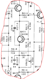
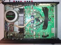
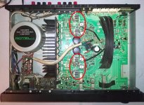
Hello sgrossklass, it's very interesting, the way you put in perspective the electrical limits of the amplifier with its mechanical limits. Here's a view inside the amp. That's right, the heatsink isn't rvery generous for a 2x40watts amp. Its size is 185L x 70 H x 40mm D.That would explain the skimpy bias levels then. This unit is quite low profile, so the heatsink basically is roughly half as big as it would be in a more conventionally tall unit - and there's 2 pairs of output transistors on top of that. At standard bias levels this thing would run much hotter!
Ventilation slots in the case look quite adequate too me... well, maybe there could be a few more in the bottom around the heatsink, but nothing dramatic. (Those into metalworking may be inclined to grab the tools and some mesh.)
Well done... You saw it, there is nowhere 2cm under the amp, maximum 7-8 mm, the feet are really thin.However, the feet don't appear to be overly high, or does it just look like that? I would make sure that there is at least 2 cm of space below the unit, and 5-10 cm above.
It looks like Rotel did their best with the size of the box... The heatsink is screw to the bottom plate (but without thermal between, it can be something to do), and there are large holes in the botton, all under the heatsink.It is unclear to me whether and where the heatsink is thermally coupled to the case, which would certainly help somewhat. I am presuming it sits on top of the bottom case. If it's already at ground potential (verify with multimeter), attaching it with some screws from below may not hurt, as well as making sure the lid is making good contact with it when closed (maybe stack some metal strips or something in between if necessary). Maybe the designers already thought of all of this, I don't know.
I gave you these other bias values to tell you that these very low bias are not rare in this brand.Actually, there is no direct relation between bias levels and output power. With a given value of emitter resistors (like 0.22 ohms), optimum bias current is always the same. It's just that the lesser models have somewhat lower supply voltages but substantially smaller heatsinks - in other words, given the same bias levels they'd be running hotter in idle! (If power supply voltage is halved, idle power dissipation at same bias level and number of output transistor also halves. However, this amplifier will only have about 1/4 the maximum power output, and probably sport a heatsink that's rather less than half the size to reflect its price.) Now an amplifier that sounds a bit worse is generally preferred over one that lets the magic smoke out prematurely, so manufacturers will tend to err on the side of caution...
Thank you for this info. It looks like these big resistors (especially R641 on my amp) have suffered with heatAlso look at R641-644, these seem to be rather toasty-looking on a regular basis apparently.
You know, when I told about my reflex because of the heat of the cover, the bias was between 9,3 and 9,7 on both channels, and I didn't destroy my amp. I can try...I am not surprised. 11 mA of bias is usually filed under "woefully underbiased", and visible crossover spikes on the scope usually disappear around the 20 mA mark in this sort of output stage. While you could afford to run an output stage with 2 pairs of transistors somewhat leaner, I wouldn't say it's a factor of 2. Maybe 25 mA each vs. 40 mA total. These amps are clearly hampered by their inadequate thermals.
I'd suggest improving thermals as suggested above and shooting for about a 5.5 mV bias level (25 mA a pair). If that gives decent temperatures, I'd be happy.
I have two questions :
- In this amp, only a bigger power voltage can augment the power output, I understood. Changing the bias will have no effect on this, right ?
- Is there, generally, a correlation between a bias increased and a change in the sound ? Perhaps it's stupid, but it sound like I lost some energy in the bass with lowering the bias...
Thank you for all your informations !!
Attachments
On Power Output
The power output depends on the ability to deliver current and this amplifier could have been designed to drive low impedance loads without clipping. The transformer would have to have low losses in the core and low stray fields to do this, and low regulation.
This could easily play louder than you would get with a different transformer with higher voltage windings. For a satisfactory job this would inevitably be bigger in size and from the picture I see no room in your chassis to accommodate anything physically larger than what you have.
If you want to put your amplifier to the test see if you can audition a similar power rated amplifier -after that you may feel more satisfied.
Yes, I would be very curious to hear this amp vs a Marantz 6005 or 6006. The three got very good reviews at their time, but one is 25 years older than the others. I'm very curious of that.If you want to put your amplifier to the test see if you can audition a similar power rated amplifier -after that you may feel more satisfied.
Output Stage Standing currents.
In a conventional amplifier design this level of bias current would be satisfactory. However in this amplifier the driver transistors work at higher currents over their conduction cycle - so the draining of base charges is not delayed as it would be with conventional drivers ramping up in current close to the crossover region - whereas with this amplifier the process is more or less constant.
Looking at the turn on region for a transistor - the base to emitter voltage versus current is curved and less than ideal with two transistor in series.
If it can be arranged that the driver transistors operate above their turn on threshold that would leave only the output transistors to consider. In that sense 11 m.V. is roughly half the 25 m.V. you have advocated.
I see the aim here is to be able to switch the output transistors as fast as possible so the transition point in the curved base emitter voltage turn on region is made smaller in duration and occupy less length / space on the curve.
An analogy might be like flat earth (away from the equator).
I am not surprised. 11 mA of bias is usually filed under "woefully underbiased", and visible crossover spikes on the scope usually disappear around the 20 mA mark in this sort of output stage. While you could afford to run an output stage with 2 pairs of transistors somewhat leaner, I wouldn't say it's a factor of 2. Maybe 25 mA each vs. 40 mA total. These amps are clearly hampered by their inadequate thermals.
I'd suggest improving thermals as suggested above and shooting for about a 5.5 mV bias level (25 mA a pair). If that gives decent temperatures, I'd be happy.
In a conventional amplifier design this level of bias current would be satisfactory. However in this amplifier the driver transistors work at higher currents over their conduction cycle - so the draining of base charges is not delayed as it would be with conventional drivers ramping up in current close to the crossover region - whereas with this amplifier the process is more or less constant.
Looking at the turn on region for a transistor - the base to emitter voltage versus current is curved and less than ideal with two transistor in series.
If it can be arranged that the driver transistors operate above their turn on threshold that would leave only the output transistors to consider. In that sense 11 m.V. is roughly half the 25 m.V. you have advocated.
I see the aim here is to be able to switch the output transistors as fast as possible so the transition point in the curved base emitter voltage turn on region is made smaller in duration and occupy less length / space on the curve.
An analogy might be like flat earth (away from the equator).
So, it sounds like your choice would be to leave the bias on the value advised in the service manual ? Right ?If it can be arranged that the driver transistors operate above their turn on threshold that would leave only the output transistors to consider. In that sense 11 m.V. is roughly half the 25 m.V. you have advocated.
Perhaps I should try to adjust it on the 3,5 mV choosen by Pingrs, This choice was taken from a serious observation of the output signal... And in fact, I'm a little afraid of using 5,5 mV, more than twice the original value.
Last edited:
Indeed yes. Manufacturers do have quality control checks which include THD testing on production lines. For servicing purposes 2.5 m.V. is likely to be typical for setting the bias in order to meet the specification.
From what you have said Pingrs amplifier is a different Rotel model- I don't know what the circuit looks like however I expect the driver /output stages would not be identical to yours and consequently the test voltage measurement would be different.
From what you have said Pingrs amplifier is a different Rotel model- I don't know what the circuit looks like however I expect the driver /output stages would not be identical to yours and consequently the test voltage measurement would be different.
No, Pingrs has certainly the same amplifier than mine. All the thread where his message is posted is about the 840-BX, but when Pingrs talks about "Strangely, my manual shows a reading of 2.5mV between TP1 & TP3 (TP2 &TP4) after the suggested warm up... ", it means that he has CERTAINLY the same amplifier than mine, a BX3 ou 4, the only versions to have a 2,5 mV bias (all the rest of the thread is about 4mv bias). That's why I'm tempted to follow his advice, and to leave it on 3,5 mV. I'll test this evening !!From what you have said Pingrs amplifier is a different Rotel model- I don't know what the circuit looks like however I expect the driver /output stages would not be identical to yours and consequently the test voltage measurement would be different.
Increasing the bias
Looking at the image of your amplifier I see the driver transistors are mounted on individual heat sinks that look to have high enough thermal dissipation for the designed needs.
When stages like this run in Class A mode the current passed is constant and these will run warmer.
Designs where resistor cross coupling of driver emitters in one case and otherwise connecting these to the load do not run constant current and run cooler. There is a bit more latitude for bias adjustments there.
The Class A operation of the driver stage is a design aspect that should not be overlooked - I have seen threads where R641 and R643 have burned out.
There appears to be a thermal cut out that has prevented further damage but nonetheless replacing these resistors is extra work that you would want to avoid.
The ratio of 3.5m.v. to 2.5 m.V. is significant in percentage terms, and increasing the bias will increase the driver dissipation. I don't see any thermal sensing on the driver transistors and deduce from this that is contained by the heat sinks and you should keep it that way.
If these are heated too much there will be flow-on effects to the output stage and a risk of creating a vicious cycle of heating effects between the drivers and output transistors.
There is always a lag in time between heat reaching the sense transistor and this making an adjustment so there is more to this than many people might think.
The risk of fiddling with the bias is to upset the delicate arrangements of unseen design aspects of optimizing the adjustment to be as close as possible in terms of sych.
Pngrs THD test for that matter was a simple test at one point in time with steady state signal input whereas music is asymmetric. His test is one consideration but not one that over arches everything else.
Increasing the bias is not to be taken lightly however if you are intent on doing this I suggest you measure the voltage drop across R641 and R643 (1k 1W) to see what level that is.
In the first instance this is to establish a reference point with the bias set at 2.5 m.V. and after the amplifier has warmed up give this a decent workout on music and check the bias and heat on the driver and output transistors afterwards.
Then repeat the exercise with the bias set to 3.5 m.V.
Last edited:
Hello, and thank you for all these informations. I have augmented the bias to 3,5 mV 1 hour ago, and I listen my amplifier, looking after the temperature...Looking at the image of your amplifier I see the driver transistors are mounted on individual heat sinks that look to have high enough thermal dissipation for the designed needs.
When stages like this run in Class A mode the current passed is constant and these will run warmer.
I was about to write a post when I could read your, to give my feeling about that.
First, the drivers you're speaking about, if they are those marked in red on the pictures, produces the heat of the cover, and not the principal heatsink. I listen my amplifier at low volume (command at 9h), and these drivers are hot, not the power transistors.
I received a private response from Pingrs about this thread :
"From my notes of Jan 2009, my Rotel RA840-BX4 (one I was given and repaired) required a bias voltage of 3.5mV to minimise the crossover spike on the distortion residual at full power at 10kHz. When cold, (20C) that bias voltage rose to 11mV L, and 11.6mV R. I can’t remember if there were any issues with heat at this setting; I don’t think so, otherwise I would have noted it."
So, what can I think ?
- I believe Pingrs, when he writes that for this amplifier, 3,5 mV is a verified ideal for the bias value.
- as sgrossklass wrote, the amp body is limited in size, and then in thermal dissipation. A bias reduced to 2,5 mv can be a preventive way to avoid excess of heat, and transistors destruction
- I think, about the design of the amplifier, that a possible upgrade is to put cones unter the existant feet : not really for the cones, but to increase the amp's height, and then the space under it, to upgrade air cooling. Larger dissipators would be usefull, too for these drivers.
- You're right about the resistors you spoke about, one of the four big in my amp (R641) lost its colour codes because of heat. But remember, when I got this amp and checked the bias for the first time, I found around 9,5 mV on both channels !
So, what will I do ? I think I'll let it a few days on 3,5 mV. I don't hear this amp loud, I told you. I will listen my amp with attention, I have it just since a few days. Pingrs will send me some scope shots he did of the crossover spikes he speaks about. And in the same time I will replace these big resistors.
When I'll have more the habit of the sound, when I will know better the sound of this amp, depending on the Pingrs shots I will reduce the bias to 2,5 mV. And if I don't hear any difference, I'll leave this value.
But I repeat that, IMHO, more space under the body, and bigger radiadors on the drivers can bring something.
Attachments
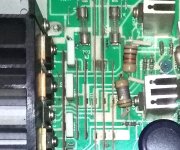
It'll be a nominal 41.6 V pretty much regardless of bias setting, for a corresponding number of milliamps to drain off base charges. We are talking about the emitter resistors in a complementary pair of emitter followers after all. One end of R641 has to be one B-E drop or about 0.55 V above output (which is at 0 V), and the other end connects to the negative supply (-41 V).Increasing the bias is not to be taken lightly however if you are intent on doing this I suggest you measure the voltage drop across R641 and R643 (1k 1W) to see what level that is.
These resistors (R641-644) get toasty since they are 2 W parts having to dissipate 1.73 W all the time. That normally would've called for at least a 3 W part.
With drivers being on their own dedicated heatsinks and at reasonably high current to begin with, I would expect less thermal drift than in a conventional full-AB output stage, so the bias circuit is likely to overcompensate heavily when warming up under load. And indeed, the values of 10 mV cold vs. 2.5 mV warmed up would seem to suggest just that happening.
Note how the service manual suggests to "run about 5 minutes with rated output (8 ohm)" - that'll warm up the heatsink considerably. So the idea is to have it run at 2.5 mV when the main heatsink is decidedly warm / hot, not when it's just idling away. This will protect the unit under load. At modest listening levels, bias would be expected to be a good bit higher. This scenario would make a lot more sense to me.
This output stage setup should be somewhat less prone to crossover distortion indeed. Class A drivers + low effective Re, and the better SOA provided by doubled-up outputs is always appreciated.
Last edited:
Hello, and thank you for all these informations. I have augmented the bias to 3,5 mV 1 hour ago, and I listen my amplifier, looking after the temperature...
I was about to write a post when I could read your, to give my feeling about that.
First, the drivers you're speaking about, if they are those marked in red on the pictures, produces the heat of the cover, and not the principal heatsink. I listen my amplifier at low volume (command at 9h), and these drivers are hot, not the power transistors.

I received a private response from Pingrs about this thread :
"From my notes of Jan 2009, my Rotel RA840-BX4 (one I was given and repaired) required a bias voltage of 3.5mV to minimise the crossover spike on the distortion residual at full power at 10kHz. When cold, (20C) that bias voltage rose to 11mV L, and 11.6mV R. I can’t remember if there were any issues with heat at this setting; I don’t think so, otherwise I would have noted it."
So, what can I think ?
- I believe Pingrs, when he writes that for this amplifier, 3,5 mV is a verified ideal for the bias value.
- as sgrossklass wrote, the amp body is limited in size, and then in thermal dissipation. A bias reduced to 2,5 mv can be a preventive way to avoid excess of heat, and transistors destruction
- I think, about the design of the amplifier, that a possible upgrade is to put cones unter the existant feet : not really for the cones, but to increase the amp's height, and then the space under it, to upgrade air cooling. Larger dissipators would be usefull, too for these drivers.
- You're right about the resistors you spoke about, one of the four big in my amp (R641) lost its colour codes because of heat. But remember, when I got this amp and checked the bias for the first time, I found around 9,5 mV on both channels !

So, what will I do ? I think I'll let it a few days on 3,5 mV. I don't hear this amp loud, I told you. I will listen my amp with attention, I have it just since a few days. Pingrs will send me some scope shots he did of the crossover spikes he speaks about. And in the same time I will replace these big resistors.
When I'll have more the habit of the sound, when I will know better the sound of this amp, depending on the Pingrs shots I will reduce the bias to 2,5 mV. And if I don't hear any difference, I'll leave this value.
But I repeat that, IMHO, more space under the body, and bigger radiadors on the drivers can bring something.
If the output emitter resistors are 0.22 Ohms and these conduct 11.6 m.A. - the current deduced by pngrs there is an error. From Ohms law Voltage= Resistance times Current.
Multiplying pngrs figures together 0.22*11.6/1000 = 25.5/1000 V. That is 25 m.V. and since the numbers 2 and 3 are adjacent on the top row of a keyboard 3.5 m.V. would seem to have been a typo. You would have to clarify that with him.
Anyway I consider it advisable to replace your emitter output resistors.
Carbon resistors can drift in value due to the heat environment they live in. In the TV repair trade in the days of valve/tube sets the term was "gone high". one of yours has darkened and had it's day - if it is working it could be adding noise.
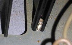
When fitting replacement resistors make sure these stand tall with long leads to maximise the circulation of air around both the leads and the body. In your photo these are too close to the driver heat sinks and the pcb.
If you cut the old parts out close to the resistor bodies you can double the mass in the leads by strapping the remnant in the pcb to the replacement lead. You can do this by twisting a fine strand of tinned wire around the separate ends and solder the combination at those two points.
This is a method used by repair men which obviates the time and cost of disassembly and reassembly of the unit.
Last edited:
Hi to sglossklass and mjona,
twi things :
- yesterdays, when I vas listening my amp with bias at 3,5 mV, I didn' t noticeany abnormal heat, it was hot.. as usual.
- a few minutes ago, I did some measures on the Rotel, to see if what I see is like Pingrs found on his amp. And I checked the bias just after powering the amp;, and after i took some measures during the 20 first minutes. The cover was off, of course, so a much better air cooling for the radiators, and no heating to the nominal power before.
Channels .R.......L
At T=0 ...0,8 ...1,0
+ 15 sec .1,0... 1,2
+ 2 min ..1,4... 1,6
+ 4 min ..1,8... 2,0
+ 6 min ..2,2... 2,4
+ 10 min 2,8... 3,0
+ 12 "" ...2,9... 3,1
+ 14 "" ...3,1... 3,2
+ 16 "" ...3,1... 3,2
+ 18 "" ...3,2... 3,3
+ 20 "" ...3,2... 3,3
So, not like for Pingrs, my bias increases with the heating time.
- Status
- This old topic is closed. If you want to reopen this topic, contact a moderator using the "Report Post" button.
- Home
- Amplifiers
- Solid State
- Thank you! From a Rotel RA-840 BX4 owner