Hi All,
I have an Arcam Alpha 8R which was blowing fuses (mains T1.25A) immediately when powered on.
Kicking myself on this one as the fault was self inflicted when I managed to short the speaker output on one channel.
I know a little about electronics so did the tests below with no power to the amp.
1. Found output MOSFETS shorted on faulty channel.
2. Checked all smaller transistors which metered fine.
3. Checked PSU and diodes which metered fine.
I followed the instructions in the service manual and:
1. Replaced the output transistors and insulators.
2. Checked no short between MOSFET and heatsink.
2. Adjusted the bias trim pot fully anticlockwise as per service manual.
I powered on amp and power LED came on orange and then turned green (Normal). After about one minute the amplifier blow the mains fuse again.
Again the same channel MOSFETS were blown.
I can only think of a couple of things that would cause this. Maybe someone with experience will know more in this respect.
1. The original MOSFETS were obsolete (ST Microelectronics IRF540).
I replaced them with IRF540N(PBF) Infineon MOSFETS from Farnell. Order Code - SC08216.
I bought them from Farnell to make sure they are genuine.
* PBF designation is only to do with eco friendly I think.
I was wondering if my substitute MOSFETs were correct.
2. Only other thing I can think of is the amplifier may be going into oscillation but everything meters OK.
Hoping to save the amp from the dump and my ears from the sound of the TV so any help would be appreciated.
I have access to an oscilloscope if necessary.
Attachments
I was wondering if my substitute MOSFETs were correct.
Not entirely, the mosfets you have installed have ~ 2.25 times more input capacitance (Ciss) than the original mosfets (870pF vs 1960pF), therefore it will load ~ 2.25 times previous driver stage - try to find the original ones.
Also, in cases like yours, the driver stage is also affected (damaged) as well as protection circuit (it seems to work properly in your case), so my advice is to change ALL small driver transistors (BC546B/BC556B) east from VAS stage starting from Q3/Q4/Q5 and Q17/Q18/Q19.
Thanks for the responses.
Should have mentioned the right channel is the faulty one.
Didn't have time this weekend to do anything but I have another 2 IRF540N(PBF) which I can try.
Mooly - I have heard about the light bulb protecting the amp. I was going to wire a light bulb in series with the 230v live input to the amp. How does this work? Looks to me like it would put a reduced voltage into the amp.
I'll try and change the MOSFETs and contruct the dim bulb tester tomorrow night and update you.
The filament behaves as a non linear resistance. When its cold, or when little current flows its resistance is low. That allows almost full voltage to appear at the amp. If the amp draws to much current the filament heats and its resistance increases dramatically both lighting the bulb and as a consequence limiting the current to the amp.
Managed to spend some time trying to repair the amp again after being on-call last week.
I tested the transformer to be certain there was no issue with that. Disconnected secondary transformer leads from board.
Powered amp on and does not blow fuses. Measuring about 39v on both secondaries with no load.
Looks like transformer is OK. There is a lower voltage for the volume remote control which is OK.
I also sourced more IRF540 MOSFETs same as originals.
Replaced parts below:
Blown MOSFETs Q101 Q102.
Zener diodes - D102 D103 D014
Transistors - Q103 Q104 Q105 Q114 Q115 Q117 Q118.
Thought Q110 and Q119 were short circuit but checking the circuit diagram the base is connected to the collector on both transistors. I think they are part of a constant current source.
Also made Dim Bulb Tester as per Molly's advice. Adjusted trim pot on faulty channel to high resistance.
Powered up amp with DBT connected using 100watt bulb in DBT. Light bulb glows initially then goes out. Amp LED stays green after a few seconds.
Faulty channel (right) MOSFETs heat up while left channel MOSFET's are very cool.
Quiescent current is stable at 2.5mV on good channel and is about 7mV on faulty channel. Recommended is 3mV so the faulty channel cannot be adjusted down any further. Looks like there is still a fault.
Measured DC on both rails. +38volts and -38 volts respectively.
That's all I have done so far. Don't want to leave the amp on too long while testing.
Any suggestions for further testing would be appreciated.
The transistors with B connected to C form current mirrors.
It all sounds pretty promising at this stage. Is the DC offset close to zero on the repaired channel? That is the DC voltage at the amplifier output.
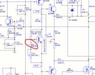
Depending on how the original circuit is designed with regard to component tolerance (such things as Vgs of the FET's) you may have to tweak the value of R152 which is shown as a 3k9 resistor in series with the bias preset.
Try a 5k6 or 6k8 here and see if the bias can be brought down to the correct value.
And keep using the bulb tester for this.
It all sounds pretty promising at this stage. Is the DC offset close to zero on the repaired channel? That is the DC voltage at the amplifier output.
Depending on how the original circuit is designed with regard to component tolerance (such things as Vgs of the FET's) you may have to tweak the value of R152 which is shown as a 3k9 resistor in series with the bias preset.
Try a 5k6 or 6k8 here and see if the bias can be brought down to the correct value.
And keep using the bulb tester for this.
Attachments
Bit of a belated reponse after a year. Found a spare Pioneer SA-410 among my hoardings which stood in for a while.
You were spot on Mooly. Turns out I needed slightly larger resistor values than you suggested. The nearest I had above the 6K8 was a 10K resistor. Fitted that which did the job. Adjusted quiescent current to 2.5mV as per service manual. Output transistor temperature cold at no input. There is -20mV offset at the speaker terminals which seems acceptable.
Tested on the "Suicide Speakers" (8 ohm car speakers) for a few days and then connected back into the system speakers and working as normal.
Thanks a lot for your help Mooly. Much appreciated.
")
- Status
- This old topic is closed. If you want to reopen this topic, contact a moderator using the "Report Post" button.
- Home
- Amplifiers
- Solid State
- Arcam Alpha 8R Amp blowing fuses