Thanks, Everyone, for the help --
About the Heatsink Ground to the Common by the 100 Ohm resistor: Yes, I did try grounding it directly, no change, but that was before I removed the Power Mosfets for the latest exercise. -- (I measured any Voltage across that resistor before doing so)
But I will Check those AC Feedback Capacitors C722 and C714 to be sure.
Mooly: I'll measure the Voltage across the R717, and Post the results. Maybe We are starting to get somewhere! Probably do that in the morning as it's getting late here.
Thanks for All --
Hi Mooly
Looks like the voltage across the R717 in both Channels is:
LH: .255 Volts, -(81.1 Ohms);
RH: .261 Volts, -(82.5 ohms) Calcs show 3.14 and 3.16 mA respectively.
The DC Voltage across those 56 Ohm Gate-Source Resistors measures an average of
2.4 volts, so looks like there is about 42.8 mA flowing in those. Do you think that changing them to 10 Ohms might still be a good idea?
Have yet to check those 10pF Feedback Capacitors C722 and 714, will do later today --
THanks for all!
Those voltage/currents for R717 are a little lower than I suggested at first but I have just thrown that current sink into a simulator and got a value of 3.7ma so we'll say all good there.
Lowering the G-S resistors more could actually pull to much through the drivers (depending what's fitted). I suspect you've proved the point really and that is that it still oscillates.
I can't really think of anything to suggest because having both channels with the same problem suggests something common to both has been replaced at some point and is causing an issue.
These older designs can be very device dependent (semiconductors) often partly relying on the specs of the semiconductors as part of the whole stability scheme. For that to be the case though, the amp would have been like this all along and not suddenly have failed.
Mainly only the Power Supply, and the Protection Circuitry, and, of Course, the Earthing/Grounding, which Tomorrow I will Check EVERY Track, and make sure.
So Far, I have not checked those Feedback Capacitors C722 and 714. I will Perhaps Carefully Remove them from the Pcb and just substitute the Correct Value - (5pF), and see what the result is. If the same, maybe Slightly Increase the Value?
Thanks for all!
So Far, I have not checked those Feedback Capacitors C722 and 714. I will Perhaps Carefully Remove them from the Pcb and just substitute the Correct Value - (5pF), and see what the result is. If the same, maybe Slightly Increase the Value?
Thanks for all!
The links below are videos of troubleshooting multiple issues in a Hitachi HA-4700 receiver. One of the issues addressed was oscillation in both channels. The solution was increasing capacitance of (I believe) Miller caps in both channels. The author(?) surmises that the original design had been barely stable, and that slight component value drift over time had caused the design to become unstable.
The amp circuitry does not look like the amp in this thread. But perhaps it is possible that some members of the same design team had a hand in both amps.
Anyway, for what it may be worth...
Part1: YouTube
relevant info at 25:40
Part2: YouTube
relevant info at 3:34, 6:33, 8:22, 9:15-10:08
The amp circuitry does not look like the amp in this thread. But perhaps it is possible that some members of the same design team had a hand in both amps.
Anyway, for what it may be worth...
Part1: YouTube
relevant info at 25:40
Part2: YouTube
relevant info at 3:34, 6:33, 8:22, 9:15-10:08
Last edited:
Thank You so much --
Those 2 circuits do look a little similar; Those Capacitors the Author changed went to 10 times the Original Values; from 2 x 22pF in series (11 pF) up to 100 pF. Maybe I will try somthing like this on the Vertical input Pcb with those 2 x 10 pF in series.
Maybe, as suggested, there could be a similar problem in this HA-6800.
I can't see that Changing these can do anything but slow the circuit down.
I'll Post the results --
YIf you hit a dead end you might want to try the procedure on page 14 of AN-1645 LM4702 Driving a MOSFET Output Stage 7.1 Determining Gate Resistor Values
Page 7 "1.6 Parasitic Oscillations" of cordellaudio MOSFET Power Amp.pdf might be interest
regards
james
Page 7 "1.6 Parasitic Oscillations" of cordellaudio MOSFET Power Amp.pdf might be interest
regards
james
Last edited:
Well, I watched that Video on the HA-4700 repair, and decided to do similar on this one, to see what happened. I checked those Capacitors C722 and C714, in both channels, both perfectly okay. Then, I bridged them with 100 pF as suggested.
Problem Solved! -- Rock Stock Stable, even with big changes of supply voltage, unlike before. Next, I will connect the Sig.Gen, and feed in a signal to see what the response looks like, before I refit those Power Fets. I dare say that this mod might affect the Highest Frequency Response, But, I'll see by how much.
I'll be posting the results.
Thanks for All!
If 100pF stopped the oscillation, then perhaps a smaller value (but larger than original) would as well. As I recall, the technician who made the video only tried one non-original value which, as you noted, was significantly higher than original.
Interesting to read of your test results. And I hope this is a legit method...if it is not then hopefully someone will explain why.
Interesting to read of your test results. And I hope this is a legit method...if it is not then hopefully someone will explain why.
Wait...722 & 714? I don't believe those caps are serving the same function as the ones that were changed in the HA-4700
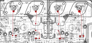
In the HA-4700 I think those are miller caps, from base to collector of the VAS, whereas in your amp the similar looking caps are in the NFB loop (from the schematic on pg 2 of this thread).
Anyone who wants to see go to 6:47 (where the author is pointing at the caps in question with a pencil) in the 2nd of the two videos I linked earlier, and repeated below
YouTube
Last edited:
Hello, All
Thanks for all the suggestions -- What I did next was to Lower that 100pF Capacitor to 50pF; still Rock Stable. I then Injected a Test Signal into the Aux Input for that channel, and swept the frequency to see the response. It still looks reasonably flat until 40 Khz, until it starts to taper off gradually. It is only about 3dB down at 60Khz, still a perfect sine wave with no sign of instability.
That's correct; those caps are the AC Feedback devices.
Is there any thing someone might suggest I do before refitting those Power Fets?
I've no answer as to what has gone on here. Post #1 suggests you acquired the amp minus its output devices and so that still leaves the possibility that some unknown work might have been done in the past.
I guess you have to just fit the FET's back and see how it all behaves.
I guess you have to just fit the FET's back and see how it all behaves.
Hi All
Well, Refitted the Output FETs and now have discovered that there is Still Oscillation, Both Channels; maybe I'll dive back in and have a go with what was suggested a couple of posts back; Perhaps try adding a little bit of Capacitance across the Base/Collector Junctions of Q706 and/or Q707, (just as Hitachi has done in the HA4700 across the Q702/Q703 junctions).
Do You think that this might solve the problem? -- Was rock stable until I refitted those Output Devices.
No magic answers I'm afraid ") Adding capacitance at strategic points in a circuit will often tame instability, but ultimately the reasons why this has to be done really need addressing.
Adding capacitance at strategic points in a circuit will often tame instability, but ultimately the reasons why this has to be done really need addressing.
For example, whether it really is a marginal design stability wise, or whether alternate semiconductor replacements have changed the characteristics and altered the phase margins.
Adding capacitance at strategic points in a circuit will often tame instability, but ultimately the reasons why this has to be done really need addressing.For example, whether it really is a marginal design stability wise, or whether alternate semiconductor replacements have changed the characteristics and altered the phase margins.
- Status
- This old topic is closed. If you want to reopen this topic, contact a moderator using the "Report Post" button.
- Home
- Amplifiers
- Solid State
- Hitachi HA6800 Problem