Hello again
Looking for the Mosfet Output Stage Experts!
Had this Hitachi HA6800 Amp for a while, been working perfectly, Lately, started to sound a bit odd, so I replaced the remaining Fusible Resistors, some of which had altered in value. No difference, so I started looking around for other things. I found that the Speaker Coupling Relay was suspect, so I replaced it with a 24 Volt higher current version. Still no change. Then, I discovered that The Main Bridge Rectifier S5VB-20 had one Internal Diode that had a very High Forward Voltage Drop, so I replaced it with a much better device. Still no difference, so I then checked the ESR of the Two Main Power Supply Electrolytics, which were a bit high at about .4 of an ohm. As the inside of these Amps run rather warm, as a result of the High Idling Current, I then replaced those Two Capacitors with ones of both a
Higher Capacity and Higher Voltage. -- Still no Change.
When I initially first repaired this amp in 2011, I Replaced the Mosfet Output Devices, which were originally 2SJ48 and 2SK133 -- (Which were missing) with the more modern 2SJ56 and 2SK176, which appeared to have the same basic specs. The Amp then set up correctly, and has been running perfectly since that time, until now.
What I have found is that it is tripping on the protection circuitry, NOT from DC levels on the Output Rails, but by excess Current in the Source Coupling Resistors, which are monitored by the protection circuit. I have looked carefully at the output rails on the Scope, and it does look to be rather noisy, but not when Simply Idling. Trips on signal in Either Channel, as soon as you start to ramp the output.
Is it possible that the output Stages are 'taking off' with an applied signal?
If needed, I can Post the circuit schematics of the Power Amp. The Amp has ben recapped with good branded capacitors. The Voltage levels To Ground between all parts of both channels are practically identical, so something must be right --
Any Advice will be GREATLY Appreciated! -- Thanks so much!
I think we need to see the circuit details tbh.
An amp that suddenly draws current when a signal is present suggest HF instability. That should show on a scope. It seems odd if both channels are suddenly doing this though.
I would also look over ALL work that has been done and be 100% certain that no incorrect value parts have been fitted.
An amp that suddenly draws current when a signal is present suggest HF instability. That should show on a scope. It seems odd if both channels are suddenly doing this though.
I would also look over ALL work that has been done and be 100% certain that no incorrect value parts have been fitted.
So a lesson here has been learnt.
Using 'better', 'larger', 'higher voltage' components do not improve matters. After all, the designers probably know a bit about what they are doing.
Always use the same type of component for continued safety.
Fuseable resistors are designed to fail under stress and MUST be replaced with exactly the same type and values otherwise their job will be compromised.
That said, if R715L or R get tarnished and go high in value, excessive current will be drawn and cause issues as you have described.
Attachments
Many Thanks to JonSnell and Mooly for the help! But, where on earth are You able to get those fusible resistors? I have looked in various component suppliers such as RS Components here in New Zealand and found nothing, so in the end, I replaced them with the smallest wattage devices I could find, ie; 1/8 watt.
I will now go back over the amp, and check what has been offered --
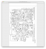
Also, Thanks to JonSnell for posting the Schematic of the Power Amp.
Thanks so much!
I will now go back over the amp, and check what has been offered --
Also, Thanks to JonSnell for posting the Schematic of the Power Amp.
Thanks so much!
Last edited:
There's a copy of the service manual here:-
Hitachi HA-6800 - Manual - Stereo Integrated Amplifier - HiFi Engine
You do have to register to access it, but it's free. There may be more useful info there.
Hitachi HA-6800 - Manual - Stereo Integrated Amplifier - HiFi Engine
You do have to register to access it, but it's free. There may be more useful info there.
Hello
Thanks so much for the offer, But I have that already, had to pay for it back in 2011!
Progress again so far: I have checked all of the replacements fitted so far, all are correct, but that was a good idea to check. I have discovered that the Amp would appear to be oscillating at a High Frequency that I can't actually measure, so as suggested this is definitely what is wrong.
Now, to find out why -- I am going to have a good look around with the Scope
and will post whatever I find -- Thanks for all the help!
I have been looking closely with my Good Scope, and have discovered that the Amp is indeed oscillating at a high frequency, so this is causing Instability when trying to amplify an audio signal.
Whai I did then, was to remove the Output Mosfets, as they are only plugged into sockets -- easy.
Then I closed the AC/DC feedback loop by connecting a 56 Ohm Resistor between the Gate terminal and Source terminal of Each Device, (both channels). This is a Source Follower Output Stage.
I have done this in the past to find other problems in BiPolar Amp Output stages with much success.
However, after I carefully Powered it up using a Variac to be sure, I find that Both Channels are Oscillating at what the Freq. Counter reads to be over 230 Khz, sine wave, perfect. -- Output rail is 4 Volts Peak to peak.
The Output Rails are sitting at about 12 Millivolts DC, so DC wise looks to be good.
I would have thought that the Input/driver stages would be Perfectly Stable,
(as I have seen in the past with other designs) -- Is there something here that I am missing?
After all, if the Output Fets are being supplied with something that is taking off, how can the complete Amp ever be stable?
Maybe my 56 Ohms is too high? -- Phase Shift somewhere?
Any Comment would be greatly appreciated -- Thanks for all --
Hi, Mooly
Thanks for that. -- Yes, it's both channels, the Frequency of one looks to be at about 234Khz, the other about 262 Khz, and reasonably stable, according to the counter.
This does Vary with a change of Power Supply Voltage; the higher the voltage, the higher the freq. and the more output voltage, to me a classic sign of taking off!
All of the Other Devices are Absolutely Original, the only thing different is the replacement of those wrong-value Fusible Resistors and my recapping of the front end, all of which has been double checked and only done since this problem began. I have been very careful in the mounting of any replacements to make sure that the lead shapes and lengths are exactly the same as the replaced parts.
I see that Jonsnell has been good enough to post the Schematic of the amp.
Do you agree with the method of removal of the Output Devices to fault find in a Mosfet Power Output Stage?
Very very odd that both channels should be the same. On the face of it that suggests something common such as supplies or grounding.
Are you 100% sure all those fusibles have been replaced with correct values, in particular any that determine standing current in various stages of the amp.
An incorrect electrolytic almost certainly wouldn't cause this but an incorrect value of some of the smaller film types would, so if you have replaced any of those then check.
Running without outputs as a test is fine as long as it works, but its not universally guaranteed to work on all designs.
Thanks for that -- The Only Electros I Replaced were C715, 100/6.3v, C721, 10/16v, (Bipolar), and C705, 10/16v, on the Vertically mounted Input Card.
No Replacement of Mylars or Film types as they all measured OK.
And Of Course those Main Filter Caps in The Main Power Supply.
But, I'll Check on all Values, again -- Good Idea -- Thanks --
No Replacement of Mylars or Film types as they all measured OK.
And Of Course those Main Filter Caps in The Main Power Supply.
But, I'll Check on all Values, again -- Good Idea -- Thanks --
Hi Mooly, Thanks for that --
No, Checked them, The 4.7 Ohm Resistors and the .047uF caps this morning.
I'm beginning to run out of ideas!
Do You think it would be safe to remove those 56 Ohm Resistors, and tie the Mosfet Gates straight to the Sources (and power up carefully) to see what happens?
-- Just an idea --
No, Checked them, The 4.7 Ohm Resistors and the .047uF caps this morning.
I'm beginning to run out of ideas!
Do You think it would be safe to remove those 56 Ohm Resistors, and tie the Mosfet Gates straight to the Sources (and power up carefully) to see what happens?
-- Just an idea --
Last edited:
www.wagner.net.au have fusible resistors in 1/2, 1 and 2W ratings
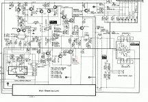
see the attached pic of the power amp section, the red square is a ground for the heatsink?, have have become lose or corroded, as its the only thing i can see thats common for both channels.......other than the protection circuitry.
Another thing I'd check would be the little pF ceramic caps like c722 c714
regards
james
Attachments
- Status
- This old topic is closed. If you want to reopen this topic, contact a moderator using the "Report Post" button.
- Home
- Amplifiers
- Solid State
- Hitachi HA6800 Problem