In a nutshell...everything works except the meter function. The relays engage, there is sound output. Both speakers.
The meters, however, blip on startup, and peg to the LEFT...below the 0 mark, and stay there regaerdless of preamp input.
Been a while since I've had this in the system, but I remember I had a problem with an equalizer (EQ35) that would spike the meter to full right and the amp would shut down. Seems like the meters still worked after I dumped the EQ, but maybe not.
I see nothing visibly wrong..no blown caps,, ICs etc., and I have resoldered all suspicious solder joints.
I'm thinking the EQ spikes may have trashed the meter driver and/or op amps. Any ideas would be appreciated. I can attach the M504 schematic if that would help...
Thanks
Gtreeting from the Colonies. I have checked the voltages on the meter driver...all pins read spec...I checked the voltage on Q606 and Q607...one IC shows correct voltage...one does not...does this necessarily mean that the IC with the bad reading is indeed faulty and should be replaced, or is there something along the line that could be causing the bad value? I find current on only one side of the relay circuit PC board. The amplifier works normally otherwise, and outputs great sound..
The meter circuit seems to pull information from the relay circuit PC board...this boardshould receive power fromthe main and meter amplifier board...the meter driver--q603 seems OK..all the voltages are correct..one of op amps- Q606- has voltage, one does not...
Attachments
Its a surprisingly complex circuit... and like a map, the bit you want is on the edge of the page.
Definitely check the supplies first. Pins 8 and 4 of Q606 should have -/+21 volts.
If you apply a short across Q604 and Q605 (collector to emitter) I think the meters should fall to around zero and stay there. Worth checking that happens.
I would also imagine that all the other pins on Q606 should be close to zero.
Is the relay RL601 closing ? That relay seems exclusively meter related.
The section from Q603 output to Q606 input isn't on the diagram. Q603 looks to be single rail. Check its supply voltage is correct and check the other voltages as best you can with respect to the diagram.
Thanks for the help. Q603...is the meter driver...all 9 pins are spec voltage...since Q603 is getting power I assume relay 601 is working. The opamp shows 21.5 (spec) on pin 4 but
only 3.9 on pin 8...btw the schematic covers allof the circuitry...perhaps you received only one half of it...please advise jim
btw the meters peg full left, below zero, and stay there...
only 3.9 on pin 8...btw the schematic covers allof the circuitry...perhaps you received only one half of it...please advise jim
btw the meters peg full left, below zero, and stay there...
Never assume anything... golden rule of faultfinding ")
If the relay is closing correctly then you should be able to measure near zero ohms between pin 1 of the opamp and the meter plus terminal. As confirmation, pin 1 and the plus terminal should also have zero voltage differential between the two points.
If both meters are behaving the same then you really should be looking at the power supplies first.
Not necessarily. The circuit is complex and appears to have presets to trim out the offset generated by the single rail front end of the circuit. These controls are referenced to the opamp supply rail and so any variation in the rail will alter the rest position of the meter.
You need to check both rails on that opamp before doing anything else.
You need to check both rails on that opamp before doing anything else.
Well, I'm getting in deeper...measuring between pin one and the meter plus terminal shows 7.48 or so on my rinky dink ohm meter...not 'near zero' ...btw sorry to bother you but there is not an electronics repair facility near 100 miles of my home in Ocala...pretty much on my own here...such as it is...
Its no bother at all It is what we like doing.
For measuring this continuity from pin 1 to the meter is one time we do this with the amp on. Normally all resistance checks are with the unit off, but here we want to make sure it is closed when it should be.
Measuring to see if there is any voltage between those two points is also good proof. If there is voltage present between the two points then there isn't continuity.
It is what we like doing.For measuring this continuity from pin 1 to the meter is one time we do this with the amp on. Normally all resistance checks are with the unit off, but here we want to make sure it is closed when it should be.
Measuring to see if there is any voltage between those two points is also good proof. If there is voltage present between the two points then there isn't continuity.
Update...yes...tests were made with power...low resistance between pin 1 at op amp and plus on meter...voltage measured from ground is the same at pin 1 and at the meter...as i mentioned, the voltages at Q441 and Q442 were off the mark...I pulled Q442 from the circuit and the meters no longer
peg but stay at zero...it wasn't hooked up to input and speakers and tested...but those transistors are definetly part of the meter circuit...doesn't mean they are the problem...just another clue?T
ested Q442 (2sa815) on the meter diode function...it's dead...a control transistor I tested checked out as it should...so I trust the meter...I believe 2sa815 is a complementary transistor to Q441 (2sc1625) The amplifier still powers up and the relays click...so...
Sounds like progress Those two transistors don't need match or be complementary, they are each used independently and any cooking grade device of suitable specs will be fine. Even something like a TIP42C (must be the C version which is 100v rated). Whatever you have really.
With the transistor out you should be able to measure the approximate -22 volts across Zener D452 and that should be stable.
Those two transistors don't need match or be complementary, they are each used independently and any cooking grade device of suitable specs will be fine. Even something like a TIP42C (must be the C version which is 100v rated). Whatever you have really.With the transistor out you should be able to measure the approximate -22 volts across Zener D452 and that should be stable.
Yes...I have the -21.2...lots of power in that area...so I guess power supply isn't a problem?BTE the unit powers up without that transistor...but no relay click...I dumped most of my parts bin when I moved...figures...all I can find is a C4512...guess the china deficit will increase once again
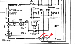
The search continues. I have ordered a replacement for the A815...SC1625 checks out as good (pulled from the system) according to the meter. Tell me why I have no power at all on the Relay Circuit PC board? On the chematic it is identified as NAOP 2810 1...it is full of capacitors and coils and resistors...yet there is no voltage anywhere on that board except 13 volts coming in from JC205...it stops there...I think the meter circuitry gets its input form this board...
Thanks for the kind words
Concentrate on getting those rails correct to the meter drive circuitry first, and then we can see where we are up to. The meter offset calibration may need altering when all this is done because it is tied to the absolute value of those supplies.
Concentrate on getting those rails correct to the meter drive circuitry first, and then we can see where we are up to. The meter offset calibration may need altering when all this is done because it is tied to the absolute value of those supplies.
- Status
- This old topic is closed. If you want to reopen this topic, contact a moderator using the "Report Post" button.
- Home
- Amplifiers
- Solid State
- Onkyo M504 meter malfunction