The calibration procedure seems straghtforward...not yet sure the transistors are the problem, but voltage on their pins was off the track...as I understand it, that could also be caused by bogus voltage going to the transistors? Say over/undervoltage from a faulty resistor?
Guess we'll see...thanks again for you knowledge
Guess we'll see...thanks again for you knowledge
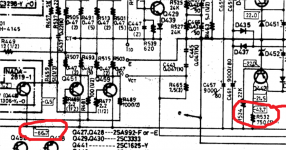
Checking the voltages with the transistors removed shows Q442 getting 70v after resistor 531..should be 43.7...441 is getting 67.2 after the resistor 532, should be 43.7..does this tell you anything?
As soon as transistors was removed there isn't any voltage drop in any of 531,532.
In this case you measure the rail voltage here.
Circuit diagram indicate voltage under normal conditions.
If rail voltage is +/-70v then voltage drop in 531 is 70-57.5=12.5v
Current through 531 is 12.5/750=0.016A or 16mA.
Last edited:
The voltage rises because no current is being drawn. Its absolutely normal.
70 volts going in to the resistor and say 43 volts on the other side means the resistor is dropping 27 volts. Ohms law tells us that means a current of I=V/R or 27/750 is flowing which is 0.036A or 36 milliamps. That current is what the meter drive circuit consumes.
Those resistors both help protect the circuitry (a bit like fuses... if they are overloaded then they will burn and go open circuit) but they also take some of the strain of the transistors. Without the resistor, the transistor would still work correctly but it would then need to drop the full differential of 70 volts less the wanted supply of 22 volts. The current would be identical and so that means the transistor would be dissipationg a lot more power and need large/r heatsinks.
43v less 22v means the transistor drops 21 volts. At 0.036A that means the transistor dissipates (W=I*V) around 0.75 watts. Just about doable without a heatsink.
70v less 22v means 1.8 watts dissipated. That needs a moderate heatsink.
So once you draw current from the 22v rail the voltage on the resistor will fall.
So that ^ sounds like the transistor was open circuit. That's actually a pretty common failure mode with the base/emitter junction going open/high.
If you had the correct -22 volts on the base and anything less than -21.2 (ish) on the emitter then the device is faulty. The base/emitter junction should drop around -0.65 to -0.8 volts in normal operation with the base being the more negative of the two. Its the opposite for the NPN one above, there the base is the more positive (by the same amount).
If you had the correct -22 volts on the base and anything less than -21.2 (ish) on the emitter then the device is faulty. The base/emitter junction should drop around -0.65 to -0.8 volts in normal operation with the base being the more negative of the two. Its the opposite for the NPN one above, there the base is the more positive (by the same amount).
The manual I have actually shows -43 volts and -67 but of course these are only approximate values and will depend on such things as absolute mains voltage.
Its understanding the theory of how it works that can help in fault-finding")
Yes Mooly, we see the same manual but the opposite polarity!
I look at the positive rail.
Attachments
Last edited:
Don't stress over the exact voltages on the unregulated side, they can vary by a good few percent either way. What we want is the -/+22 (approx. ) rails to be correct. They will be whatever the Zener voltage is less the magic base/emitter forward volt drop of around 0.7 volts.
) rails to be correct. They will be whatever the Zener voltage is less the magic base/emitter forward volt drop of around 0.7 volts.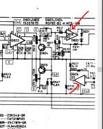
I'm confused with your process....well...put in new transistor SA815...no change...meters still hard left...below zero and not moving...maddening...haven't rechecked voltages yet...too frustrated...thing might hurt someone when I throw it out the window...ha..
BEFORE you replace series voltage regulators(Q441,Q442) has you measure for +/-21v?
If voltage was present why you replace those?
If voltage(+/-21v)was absent(but +/-68v is present),two things are posible,bud transistors or diodes or a short circuit AFTER series voltage regulators,like shorted capacitors or anything.
BTW now you have replace the series voltage regulators,measure direct on the collector,what is your measurment?
Measure direct on the base,what is your measurement?
Measure direct on the emitter,what is your measurement?
Last edited:
Up-date: Q442 voltages
Emiter measures 21.2 Schematic indicates 21.5
Collector measures 43.7 Schematic insidcates 43.7
Base measures 21.6 Schematic indicates22
Q441 voltages
Emiter measures 5.1 Schematic indicates 21.5
Collector measures 70 Schematic indicates 57.5
Base measures 3.9 Schematic indicates 22
My conclusion...Q441 is bogus...I screwed up...Q441 looked good on the multimeter transistor/diode test...wrong...with the transistors both removed from the circuit, voltage at the collector point measured right at 70v...
No one told me I actually needed a brain to do this stuff...
Q442 looks OK then, however just for reference all those voltages should be negative and quoted as such The devil is always in the detail. So black lead to chassis, and red lead to the do the poking and prodding, and you should see negative 21.5 on the emitter. You should also have the same negative 21.5 on pin 4 of the dual opamp.
Lets just be 100% certain on that because back in post #13 you mentioned Q442 being dead... which is on the negative side.
The devil is always in the detail. So black lead to chassis, and red lead to the do the poking and prodding, and you should see negative 21.5 on the emitter. You should also have the same negative 21.5 on pin 4 of the dual opamp.Lets just be 100% certain on that because back in post #13 you mentioned Q442 being dead... which is on the negative side.
Sorry...I responded yesterday to your comments yesterday but posted them improperly...replying via email...yes the voltages (opamp and transistor) you mentioned measured negative...I saw that but didn't mention it specifically...and I think I may have made an error re 442 being dead...evidently it was 441...I just misidentified iton the board...working upside down...in summary, I have a s1625 on the way...one thing, though...the schematic shows I should have +57.2 going into Q441 after resistor R531...I actually measure +70 volts with ior without Q441 in place...that's a large disparity...
The 70 volts is confusing you.
The voltage on the top end of R531 is a constant at 70 volts. The voltage on the other end of R531 varies depending on how much current is drawn from the regulator transistor.
If no current is passing through R531, then no voltage is developed across it, and that means you read the same voltage at both ends.
If you have 10 milliamps going through it then the resistor would have 7.5 volts across it, meaning you would read 70 volts at one end and 62.5 volts at the other end.
So with a faulty (open) transistor or no transistor fitted you will see 70 volts at each end.
- Status
- This old topic is closed. If you want to reopen this topic, contact a moderator using the "Report Post" button.
- Home
- Amplifiers
- Solid State
- Onkyo M504 meter malfunction