The OLG is dependent on the load resistance. Quite often overlooked.You'll also discover that the minimum risetime needs an Rload value greater than 4 ohms. At least that's my prediction.
Instructions Re 50kHz square test procedure
Bob Cordell's tutorials are subject to copyright so no images are attached. Nevertheless you can visit his website and download the zip file containing his tutorials.
Unzip this and go to Fig 19_7 and run the 50kHz square wave test to see how this compares to the circuit here.
Bob Cordell's tutorials are subject to copyright so no images are attached. Nevertheless you can visit his website and download the zip file containing his tutorials.
Unzip this and go to Fig 19_7 and run the 50kHz square wave test to see how this compares to the circuit here.
Is the phase Linear400 is also a JLH ?...
Not in the least. JLH would not approve.
mjona said "any". I happened to have the PL400 plan handy. mjona is correct: here it is "required" for current-sharing.
For single-pairs: there is no reason you can't have a resistor there. I bet I have seen it done. (Almost everything has been done.) However the quasi-complementary (NOT the same as JLH!) "needs" a resistor 'in the collector of the odd device'. Which is actually in the Emitter of the driver. So the driver feels the emitter resistor and the current in the big slave device. Since we pay for this resistor, we are reluctant to add a third.
There should be some distortion advantage, though muted by the Sziklai relationship between (say) PNP driver and NPN output.
The true original JLH is *current drive*, not a voltage-driven emitter follower.
Sorry for the digression.
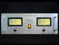
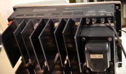
I've bought three or four Phase Linear 400s, with an eye towards refurbishment. They have a good power transformer, a good heatsink arrangement, a good chassis. All they need is a modern design using modern parts, to really shine. 200 RMS watts/channel for $1 per watt (1978 dollars). How hard could it be?
_
_
Attachments
I've bought three or four Phase Linear 400s, with an eye towards refurbishment. They have a good power transformer, a good heatsink arrangement, a good chassis. All they need is a modern design using modern parts, to really shine. 200 RMS watts/channel for $1 per watt (1978 dollars). How hard could it be?
_
They have nice VU-meters too.

I never thought about this type of chassis arrangement.
I like ! <snip>
It used to be very common for pro-sound PA amps like Crown DC300.
Easy for rack mounting, always with fan cooling.
The OLG is dependent on the load resistance. Quite often overlooked.
I used 8R in all my simulations. The rise time of the circuit looks to be about 3uS to get to 15.5V peak. I did not get my square wave exactly symmetric and considered -4.056 V and - 3.893V good enough to see whether or not there was a problem. Between these points the time was 1.585uS.
The loop gain at 100Hz is 64.4 dB which is marginally more than the circuit in Bob Cordell's loop gain tutorial and the unity gain frequency is 704.7 kHz.
I hope this is a good sign when it comes to your work on the real thing.
I'm now "back on the ranch" and have taken a quick look at the point Mark raised. There seems at first sight to be no errors in the implementation of my Tian procedure, though it was not in LTspice.
The circuit I simulated had a 22pF compensation capacitor across the feedback resistor, so Mark's calculation is incorrect as at 10MHz the closed loop gain is around 1 too. That would explain his problem interpreting the results. Maybe I forgot to include that in the circuit diagram.
Omitting this capacitor does move the loop gain to a lower frequency, but still higher than I'd expect. That raises the question about the models, so I'll continue to dig into this a little further.
Square wave simulations showed no signs of ringing on positive or negative outputs, which I had indeed checked before posting.
I'll work on building a Prasi PCB and checking that next.
Last edited:
The correct equation for the feedback ratio is, of course,
F=Rg/(Rg+1/(1/Zcf+1/Rf))
where Zcf is the impedance of the feedback capacitor, Rf the feedback resistor and Rg the "grounding" resistor.
(This is a complex number expression, just in case someone does not realise).
F=Rg/(Rg+1/(1/Zcf+1/Rf))
where Zcf is the impedance of the feedback capacitor, Rf the feedback resistor and Rg the "grounding" resistor.
(This is a complex number expression, just in case someone does not realise).
The correct equation for the feedback ratio is, of course,
F=Rg/(Rg+1/(1/Zcf+1/Rf))
where Zcf is the impedance of the feedback capacitor, Rf the feedback resistor and Rg the "grounding" resistor.
(This is a complex number expression, just in case someone does not realise).
This starts to become important at very low frequencies. The simplifying assumption (Cf=Infinity) rather than (Cf=1000 microfarads), introduces a magnitude error of 0.1 dB at 1.5 Hertz. And the error gets larger and larger, as the frequency falls farther and farther below 1.5 Hz.
The simplifying assumption also introduces a phase error. Calculating phase using the simplifying assumption introduces an error of 8 degrees at 1.5 Hz, and the error is 1 degree at 13 Hz.
Indeed. The equation dealt with not the LF time constant but the HF. This was to explain the apparent 10MHz unity loop gain frequency.
The full expression including the LF time constant is
F=(Rg+Zcg)/(Rg+Zcg+1/(1/Zcf+1/Rf))
where Zcg is the impedance of the decoupling capacitor (1mF) in series with Rg.
There will indeed be phase errors at LF as with nearly all feedback networks using this approach, but errors of 0.1dB/1 degree well below audio band is probably not too relevant.
Last edited:
Not in the least. JLH would not approve.
mjona said "any". I happened to have the PL400 plan handy. mjona is correct: here it is "required" for current-sharing.
In fact JLH designed a quasi-complementary amplifier for Hi-Fi News and illustrated this in two books he wrote. These style of amplifiers are not picture perfect but they work.
This style of output stage might have been used in the present design. I see this approach as hard to ignore but it has been overlooked.
Project update ...
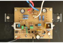
I have started to populate a prototype PCB based on Prasi's layout. There is a slight problem I didn't spot earlier (one reason to check the PCB before signing off). Will need to obtain some parts I don't have "in stock" so should be ready to test in about a week.
I have started to populate a prototype PCB based on Prasi's layout. There is a slight problem I didn't spot earlier (one reason to check the PCB before signing off). Will need to obtain some parts I don't have "in stock" so should be ready to test in about a week.
Last edited:
Retromod and Class AB.
Dear friends,
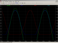
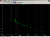
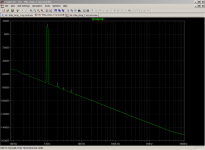
I fooled around with LTSpice. I slightly changed the circuit to my preferred mod (Retro) with bias current adjusted to ~500 ma on the outputs. In class A, the circuit can give ~1 amp into load. As I increased the input voltage, the currents increased up to 2.5 amps (Five times) just before clipping. The Voltage output to LS is about ~40 Volts, peak to peak, with just a little increase in Distortion. Please see the pics attached. Where did I goof ?
--gannaji
Can this circuit work in AB mode with high bias? If we keep the bias at say 800ma , can it give up to 10 watts in class A and then slide nicely into class B? How bad are the Distortion products in class B?
Dear friends,
I fooled around with LTSpice. I slightly changed the circuit to my preferred mod (Retro) with bias current adjusted to ~500 ma on the outputs. In class A, the circuit can give ~1 amp into load. As I increased the input voltage, the currents increased up to 2.5 amps (Five times) just before clipping. The Voltage output to LS is about ~40 Volts, peak to peak, with just a little increase in Distortion. Please see the pics attached. Where did I goof ?
--gannaji
Attachments
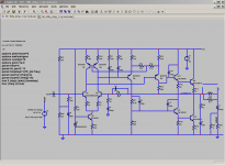
As mentioned I have now got some updates. I have completed a PCB laid out by Prasi, and this seems to work as well as the prototype.
While investigating stability of this it seems that the original choice of capacitor for rolling off the gain gave a rather low gain margin, though the phase margin was OK.
I have correspondingly increased the 100pF capacitors (C2, C3, the ones at the input stage, not the output stage driver capacitors) to 150pF.
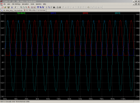
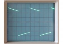
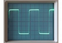
A Tian probe plot showed that 20dB gain margin could be achieved by further reducing the feedback capacitor from 22pF to 15pF. But square wave testing showed slight oscillations (well damped) in 20kHz square wave testing. This was put back to 22pF and shows better results (50kHz square wave image).
The low-power bandwidth (about 1W) is from <5Hz to >700kHz.
Distortion at 25kHz is measured at .005%
It seems this circuit will need a little more work on stability margins. but seems to be working well. Have tested with speaker but not tried excessive testing as that is too loud.
Note that Prasi's original circuit layout has a missing link, which has since been corrected. (Tr7 base to Tr1/Tr4 collectors).
While investigating stability of this it seems that the original choice of capacitor for rolling off the gain gave a rather low gain margin, though the phase margin was OK.
I have correspondingly increased the 100pF capacitors (C2, C3, the ones at the input stage, not the output stage driver capacitors) to 150pF.
A Tian probe plot showed that 20dB gain margin could be achieved by further reducing the feedback capacitor from 22pF to 15pF. But square wave testing showed slight oscillations (well damped) in 20kHz square wave testing. This was put back to 22pF and shows better results (50kHz square wave image).
The low-power bandwidth (about 1W) is from <5Hz to >700kHz.
Distortion at 25kHz is measured at .005%
It seems this circuit will need a little more work on stability margins. but seems to be working well. Have tested with speaker but not tried excessive testing as that is too loud.
Note that Prasi's original circuit layout has a missing link, which has since been corrected. (Tr7 base to Tr1/Tr4 collectors).
Attachments
Last edited:
Both Douglas Self and Bob Cordell emphasize that THD @ 20kHz is a much more sensitive test of nonlinearity, as there is less "available NFB" (another way to say there is much less excess gain) at 20kHz than at 1kHz. Image from Self 6th edition attached below.
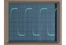
BTW your scope photo #3 might indicate some kind of a calibration issue. If indeed it IS a 50 kHz square wave, then 1 complete period of the square wave = 20usec = 3.2 horizontal divisions, therefore the horizontal sweep rate is 6.3 microseconds/division ?!
_
BTW your scope photo #3 might indicate some kind of a calibration issue. If indeed it IS a 50 kHz square wave, then 1 complete period of the square wave = 20usec = 3.2 horizontal divisions, therefore the horizontal sweep rate is 6.3 microseconds/division ?!
_
Attachments
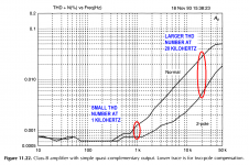
People typically set their THD analyzer to its highest available bandwidth when measuring THD at the top of the audio band. On the Audio Precision analyzers that's 80 kHz bandwidth, which just barely includes the 4th harmonic of 20 kHz. So most folks only measure AP-THD up to 20 kHz.
- Status
- This old topic is closed. If you want to reopen this topic, contact a moderator using the "Report Post" button.
- Home
- Amplifiers
- Solid State
- 16W Class A - inspired by JLH