Thanks for suggestions John,
Here is something that incorporates trimmer, B-C caps for drivers.
regards
Prasi
Hello Prasi
I have some designs that I need a pcb for .. happy to pay the going rate? shall I contact you via your web site ?
best regards
Brilliant work Prasi, thanks.
Thank you John for your kind words.
Very nice work Prasi
Being a big fan of JLH, I will for sure give this version a try. Thanks for sharing John.
BR
Eric
Thanks mate. I will post gerbers and pdfs once its finalized with kind permission from designer.
regards
Prasi
Hello Mr. PCB doctor!
Nice work!
Thanks DIY audio master
") .
. Which reminds me, I have to send you and other good friends some PCBs I had promised, almost forgot
 .
.Don't worry, take your time!Thanks DIY audio master
Which reminds me, I have to send you and other good friends some PCBs I had promised, almost forgot
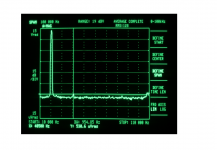
I swapped the heatsinks over. The transistors were not MJL3281A's as I thought but 2SC5200's. Similar performance, high frequency linear gain. I took no chances of oscillation and added the 100pF capacitors.
Screen shot of 20kHz at 10.3V rms- second harmonic distortion at 550uV. That's 0.005% pretty much in line with predictions.
But so similar to the 2kHz response I'm wondering if my oscillator distortion is a little high ...
A good job Prasi added the pot. as the quiescent current was slightly higher than the 2N3055's at 1.6A, creeping towards 1.7A. But did not seem to be problematic,stabilising, but will check again later.
Can't tell the bandwidth as my wide range (thermistor) oscillator has just died - think the thermistor has gone AWOL That could be a problem.
Screen shot of 20kHz at 10.3V rms- second harmonic distortion at 550uV. That's 0.005% pretty much in line with predictions.
But so similar to the 2kHz response I'm wondering if my oscillator distortion is a little high ...
A good job Prasi added the pot. as the quiescent current was slightly higher than the 2N3055's at 1.6A, creeping towards 1.7A. But did not seem to be problematic,stabilising, but will check again later.
Can't tell the bandwidth as my wide range (thermistor) oscillator has just died - think the thermistor has gone AWOL
That could be a problem.Attachments
You are probably familiar with the simple transistor current sensing constant current source (see diagram).Tr2 senses the current in Tr1 and keeps the current in Tr1 constant.
Now imagine two CCS transistors (tr3 and Tr5). If the currents in these are equal the voltages across the bases of the sense transistors (Tr4, Tr6) will be the same. So they can be joined. Now if the current in one of the CCS transistors (e.g.Tr5) increases, that will raise the base voltages, so the sense transistors turn on more. As a result they will try to reduce the current (in both) but as they share the common base, that keeps the combined current in Tr3 and Tr5 constant.
The base resistors in Tr4, Tr6 are necessary to allow the CCS transistors to swing to different currents. So they are not really CCS's but a true differential with the combined current kept constant.
The connection between the two bases (Tr4, Tr6) measures the average voltage across the two output transistors (Tr3, Tr5) through the shared connection. The other point to note is that the current into the sense side is fixed (by the previous differential stage) and that sets the base voltage, hence keeping the average voltage constant.
In practice the sense transistors usually have emitter resistors to increase the voltage drop across the resistors which set the current.
I don't know how BOb explains it but this might help.
I don't know when this circuit was first used but it seems to be common in IC design.
Thanks John
I swapped the heatsinks over. The transistors were not MJL3281A's as I thought but 2SC5200's. Similar performance, high frequency linear gain. I took no chances of oscillation and added the 100pF capacitors.
Screen shot of 20kHz at 10.3V rms- second harmonic distortion at 550uV. That's 0.005% pretty much in line with predictions.
But so similar to the 2kHz response I'm wondering if my oscillator distortion is a little high ...
A good job Prasi added the pot. as the quiescent current was slightly higher than the 2N3055's at 1.6A, creeping towards 1.7A. But did not seem to be problematic,stabilising, but will check again later.
Can't tell the bandwidth as my wide range (thermistor) oscillator has just died - think the thermistor has gone AWOL
What about difference in sound between 2n3055 and 2sc5200?
if there is pcb for sale of this marvel, I am a taker !!
+1
It will be a little longer than I thought to test the PC layout - other commitments. Should be able to get back to this in 2-3 weeks.
After a lot of early fanfare the inspiration seems to have died and it needs someone to give this a kick start. That could be you or it could be me - I'll give you the first option.
Last edited:
- Status
- This old topic is closed. If you want to reopen this topic, contact a moderator using the "Report Post" button.
- Home
- Amplifiers
- Solid State
- 16W Class A - inspired by JLH