P channel JFET as audio switch
Hi.
I recently built a 4 channel audio switch for a client. I was in a rush.
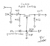
I decided to use a circuit described on the net “Audio switch notes”. It uses a P ch JFET. See the first of the two attached circuits.
It works great except that the signal gets clipped at louder transients.
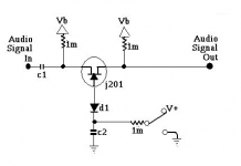
Im wondering if this is caused by the absence of a gate diode in the first attached circuit. The second attached circuit has the diode along with an N ch JFET.
Could this be the cause of premature clipping of the signal?
Hi.
I recently built a 4 channel audio switch for a client. I was in a rush.
I decided to use a circuit described on the net “Audio switch notes”. It uses a P ch JFET. See the first of the two attached circuits.
It works great except that the signal gets clipped at louder transients.
Im wondering if this is caused by the absence of a gate diode in the first attached circuit. The second attached circuit has the diode along with an N ch JFET.
Could this be the cause of premature clipping of the signal?
Attachments
Last edited:
It is a limitation of the circuit configuration I'm afraid. For the FET to be you need the gate to be negative. How much negative will determine the point the circuits 'clips'.
Its not really clipping, it is the FET being cut off by the audio signal altering the bias point. If you make the gat 5 volts negative then it should clip at a little over -5 volts negative going peak.
To turn the FET off needs the gate to be positive. This voltage will need to be higher than the peak of the voltage you are trying to block.
As it stands its not a great solution. You would be far better using CMOS 4066 switches than this.
You should connect the gate as a shunt if your source can deal with low impedance loads and your amplifier can handle a highish source impedance. This would work for the vast majority of equipment..
A 2k resistor in series with and before the JFET and modification of the drive voltage will achieve what you want. In extreme cases you may need a buffer after the shunt.
A 2k resistor in series with and before the JFET and modification of the drive voltage will achieve what you want. In extreme cases you may need a buffer after the shunt.
AgreedAs it stands its not a great solution. You would be far better using CMOS 4066 switches than this.

- Status
- This old topic is closed. If you want to reopen this topic, contact a moderator using the "Report Post" button.