Hello all, this is my first time using the forum here. (apologies if my query is not suitable for this forum)
I have a fault somebody has asked me to look at with a Denon Avr2308.
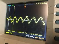
The fault is an audible 100hz hum (230v/50hz mains here) visible on my oscilloscope.
The hum is apparent after some “on time” and warming up of around 20-40mins with all inputs/outputs disconnected and with a pair of 8ohm Kef speakers connected to the front L&R channels. 230v input is not earthed (double insulated/class 2)
I assumed the hum wouldve been the main filter caps, and have replaced 4 large caps (which hasnt solved the problem) I had a poke around before pulling them out and did notice very strangely that I can manipulate the fault by blowing beside the main filter caps, the hum will go, and after 5-10seconds gradually comes back. compressed air, breath, and Same with freeze spray.
Caps were tested when removed and read around 0.1ohm ESR, shouldve been more like 0.01 i wouldve thought, which is why i decided to replace but the fault is still there.
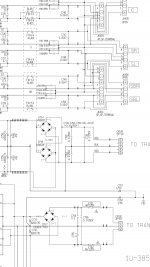
I will post a shot of the power supply schematic- Can anybody shed any light on why they are usuing an electrolytic from center tap to ground? rather than just tying it straight to ground?
I have a fault somebody has asked me to look at with a Denon Avr2308.
The fault is an audible 100hz hum (230v/50hz mains here) visible on my oscilloscope.
The hum is apparent after some “on time” and warming up of around 20-40mins with all inputs/outputs disconnected and with a pair of 8ohm Kef speakers connected to the front L&R channels. 230v input is not earthed (double insulated/class 2)
I assumed the hum wouldve been the main filter caps, and have replaced 4 large caps (which hasnt solved the problem) I had a poke around before pulling them out and did notice very strangely that I can manipulate the fault by blowing beside the main filter caps, the hum will go, and after 5-10seconds gradually comes back. compressed air, breath, and Same with freeze spray.
Caps were tested when removed and read around 0.1ohm ESR, shouldve been more like 0.01 i wouldve thought, which is why i decided to replace but the fault is still there.
I will post a shot of the power supply schematic- Can anybody shed any light on why they are usuing an electrolytic from center tap to ground? rather than just tying it straight to ground?
Attachments
So when you turn it on it's completely noiseless and after a 20-40 minutes it starts to hum, right?
First of all I would measure right after turn-on to check the good state: power rails, major GND points, critical currents, etc.
And after it goes to hum the same points. Maybe this can help to localize the problem.
Regarding to the symptoms it should be either a mechanical contact problem caused by heat or other electrolytics not the main caps.
Can you localize the problematic area with blowing air to different points of the amplifier?
Semiconductors and resitors are producing rarely such things but it's not impossible of course.
BTW: the hum is the same for both channels?
Does it change if you hit the chassis gently?
Most amps have a cross-over bias setting that depends on a pot/variable resistance. Old amps develop poor connection in connectors, switches and pots. If the bias circuit is arranged so that the bias current increases with more resistance, corrosion/oxidization increases the idle/cross-over current, which causes the output transistors to run hot and waste a lot of power and cause power supply ripple at 2x the line frequency. Use some electrical cleaner on the pots and see the bias adjustment instruction in the service manual. If you can not get a manual, a general rule is that the idle bias should be about 50mA, ie about 5mV across 0.1 Ohm emitter resistors, and the Vbe on the output transistors should be about 0.55 Volts.
There are other possibilities: You may have small electrolytic caps that have dried out and no longer decouple power supply feedback causing instabilities. Sometimes it is possible to shunt suspect caps with a similar cap to see if it fixes the problem, but doing this live is dangerous to the health of your amp, not something I would recommend to a novice.
There are other possibilities: You may have small electrolytic caps that have dried out and no longer decouple power supply feedback causing instabilities. Sometimes it is possible to shunt suspect caps with a similar cap to see if it fixes the problem, but doing this live is dangerous to the health of your amp, not something I would recommend to a novice.
Thanks alot guys. yes, the amp is sweet for the first 20-40mins, then the hum develops. i do have the service manual so should be able to check bias settings.
Couldnt see any physical issues with caps but of course they may be electrically leaky else where. the problem goes if i blow around the main filter caps, it doesnt matter if its the pair of 12,000uf or the 8,200uf caps, same result. do definitely localised to the power supply board. I am curious about that C757 1uf@50v and what purpose it has. could any of you explain why this line doesnt just go direct to ground? Thanks again for your help. i will try the mentioned points
Couldnt see any physical issues with caps but of course they may be electrically leaky else where. the problem goes if i blow around the main filter caps, it doesnt matter if its the pair of 12,000uf or the 8,200uf caps, same result. do definitely localised to the power supply board. I am curious about that C757 1uf@50v and what purpose it has. could any of you explain why this line doesnt just go direct to ground? Thanks again for your help. i will try the mentioned points
Strange phenomena with this blowing thing, this will be an interesting hunt for the root cause! ;-)
Regarding the C757 connection, could you please share a bigger part of the layout?
I'm not sure what kind of GND is "FG1"? I guess it's not the main common GND so the loudspeaker
GND is not connected to this point but rather goes to the GND point at the filter caps, right?
Regarding the C757 connection, could you please share a bigger part of the layout?
I'm not sure what kind of GND is "FG1"? I guess it's not the main common GND so the loudspeaker
GND is not connected to this point but rather goes to the GND point at the filter caps, right?
100Hz is the rectified AC ripple. It is finding its way into the audio path, many mechanisms.
Check the AC ripple on the +/-B voltage rails/at the main filter caps will be fine. More than
say 250mV (AB?) could indicate a tired main cap. More likely the ripple is being induced
into an audio "wire" (but this would occur after power on, not warm up). Suggest use cro
to test base of transistors, starting from outputs then work back.
- Status
- This old topic is closed. If you want to reopen this topic, contact a moderator using the "Report Post" button.
- Home
- Amplifiers
- Solid State
- Denon 100Hz Hum AVR-2308