……Yes, but not with straight Miller compensation, which is what petr_2009's amp being on topic is.
You can have relative high slew rate with only Miller compensation if use high current in LTP.
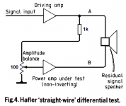
A colleague approached me and thanked me for bringing up the topic of vector distortion measurements using the Baksandall and Hafler methods.
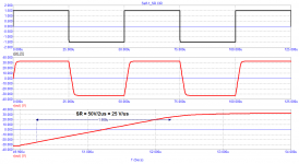
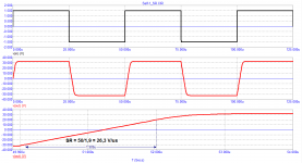
Since Hafler's method is the simplest and does not require anything other than an oscilloscope, he decided to test his amplifier using a 1 kHz square wave signal.
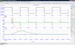
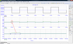
By changing the correction, he managed to reduce the signal transit time by 4 times, which had a positive effect on the sound quality. But since he did not manage to lower it below 100 ns, he decided to make a new amplifier.
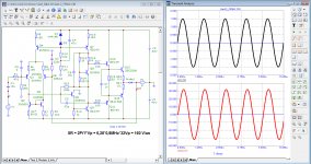
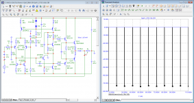
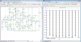
I also checked both models with this method, here are the test results
Since Hafler's method is the simplest and does not require anything other than an oscilloscope, he decided to test his amplifier using a 1 kHz square wave signal.
By changing the correction, he managed to reduce the signal transit time by 4 times, which had a positive effect on the sound quality. But since he did not manage to lower it below 100 ns, he decided to make a new amplifier.
I also checked both models with this method, here are the test results
Attachments
Of course it can be done. Pretty much anything can be done - it's just engineering.
By the way can we agree to use 'compensation' for compensation rather than 'correction', and 'square wave' rather than 'meander' for a square wave?
I understand that we are not all native English speakers (I'm not) but a common vocabulary helps understanding. Thanks all.
Jan
By the way can we agree to use 'compensation' for compensation rather than 'correction', and 'square wave' rather than 'meander' for a square wave?
I understand that we are not all native English speakers (I'm not) but a common vocabulary helps understanding. Thanks all.
Jan
Last edited:
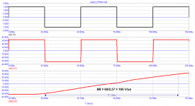
slew rate can be measured in two ways
That 2nd and 4th graph doesn't look like slew rate but rather like rise time. Slew rate would look like a straight line.
Jan
Since Hafler's method is the simplest and does not require anything other than an oscilloscope, he decided to test his amplifier using a 1 kHz square wave signal.
The upper trace, what amp generated that trace? What amp was used as a Driving amp from the picture?
BTW really smart test setup
Last edited:
By changing the correction, he managed to reduce the signal transit time by 4 times, which had a positive effect on the sound quality.
What was the nature of that effect and can you explain it?
Jan, square wave in Russian just "meander"Of course it can be done. Pretty much anything can be done - it's just engineering.
By the way can we agree to use 'compensation' for compensation rather than 'correction', and 'square wave' rather than 'meander' for a square wave?
I understand that we are not all native English speakers (I'm not) but a common vocabulary helps understanding. Thanks all.
Jan
I don't know much English, I mostly use a translator
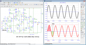
To do this, it is enough to measure the distortions of the first period (FCD), which Graham spoke about more than 15 years ago and which are directly related to the signal propagation delay time (time Propagation Delay).What was the nature of that effect and can you explain it?
I myself came to the same conclusion about 10 years ago. I learned about the existence of Graham and this branch by chance about a month ago.
Attachments
You are all trying to find some kind of know-how instead of studying fundamental theory. By itself, a decrease in GD allows you to improve the parameters, since this means an extension of the NFB coverage area with all the ensuing conclusions. This is nothing new. And I'll tell you even more - earlier Sandi Todorov pointed this out directly in the dialogue, citing an example from the english version of Jiri Dostal's book (see attach).To do this, it is enough to measure the distortions of the first period (FCD), which Graham spoke about more than 15 years ago and which are directly related to the signal propagation delay time (time Propagation Delay).
I myself came to the same conclusion about 10 years ago. I learned about the existence of Graham and this branch by chance about a month ago.
Your and Graham's first period test is essentially a step signal test and an indirect estimate of the integrator's error. And of course, widening the bandwidth helps to reduce this error.
Distortions of the first period do not exist, these are your fantasies, unfortunately and partly these are the consequences of using the simulator. With a limited spectrum input signal, there are no such effects at all with a properly designed amplifier.

Indeed, fully agree. Bruno Putzeys makes the same point, clearly explained, in his article I linked to earlier. Completely ignored except for an out-of-context statement that was used to mislead (or misunderstood).
You can't reason people out of a position they did not arrive at by reasoning.
Jan
You can't reason people out of a position they did not arrive at by reasoning.
Jan
To do this, it is enough to measure the distortions of the first period (FCD), which Graham spoke about more than 15 years ago and which are directly related to the signal propagation delay time (time Propagation Delay).
I myself came to the same conclusion about 10 years ago. I learned about the existence of Graham and this branch by chance about a month ago.
I meant the effect on the sound quality.
I will say it in simple terms. If the slew rate of the input signal is limited and less than the slew rate that the amplifier can operate, then we do not see any increase in the input differential voltage and at the output we have the same signal, but scaled. If we give a signal with a high slew rate, then the amplifier does not have time to process it and transmit it to the output undistorted. A dynamic error occurs, which we can record as an increase in the input differential voltage. In this case, the slew rate of the output voltage is limited to the maximum slew rate of the amplifier.
Distortions of the first period do not exist, these are your fantasies, unfortunately and partly these are the consequences of using the simulator. With a limited spectrum input signal, there are no such effects at all with a properly designed amplifier.
View attachment 902373
I would put it this way, distortions of the first period discussed here are entirely correlated with the transfer function of the amp and its Bode plot. They provide enough information to predict this first cycle distortion. There is no use to analyze the first cycle separately since the standard measuring technics are sufficient to acquire the same information in the form of transfer function.
I would put it this way, distortions of the first period discussed here are entirely correlated with the transfer function of the amp and its Bode plot. They provide enough information to predict this first cycle distortion. There is no use to analyze the first cycle separately since the standard measuring technics are sufficient to acquire the same information in the form of transfer function.
So, can we close this discussion?
More than 50 years ago, Baksandall investigated the slew rate of real signals at the output of amplifiers and did not find it higher than 0.5 V / μs. According to fagos, amplifiers with SR = 1 V / μs must fully meet the high quality amplification requirements. Fagos, the TDA2030 fully meets your requirements with a tenfold margin.
And what about in practice?
Slew rate calculations - how much do I need?
john curl
«Folks, I don't know if I can make better sense of everything that you are talking about, but slew rate is a LIMITING CONDITION that you don't want to approach. Do you need 500V/us? Couldn't hurt! Can you get away with 10V/us? Maybe with a bass amp, even a midrange amp, but not a full range amp, for best solid state audio fidelity.
I choose to designing about 100V/us into my typical designs, today, even though I have designed faster amps in the past.»
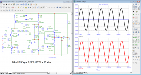
What is 100 V / μs? SR = 2Pi * f * Vp
from where FPBW = SR / 2Pi * Vp = 100 / 6.28 * 30 = 530 kHz or more for a home amplifier.
SR - speed parameter, the more SR - the less tPD!
Cyrill Hammer talked about two ways to design amplifiers:
- no NFB;
- with NFB but with a time Propagation Delay of several ns (which is difficult to implement).
In practice, it is sufficient to obtain tPD <50 ... 70 ns.
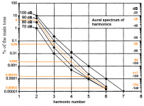
Why are non-feedback amplifiers often advantageous? The harmonic spectrum of such amplifiers is short and this is the main thing from the point of view of psychoacoustics. Cheever's work explains this effect.
Another important difference between axleless amplifiers is the behavior of the output impedance; they react to external influences instantly - without a phase shift, which is inevitable in amplifiers with NFB having the first pole below 200 kHz (AMP Hiraga)
Graham also paid attention to the behavior of the output resistance (impedance).
All other things being equal, amplifiers with lower signal propagation delay sound better. This has been confirmed by numerous colleagues who have asked me for help in finalizing their amplifiers.
I just tried to show on the simulation results what Graham claimed, but he never found understanding. On this I bow, everyone can remain with their delusions. Continue making amplifiers without paying attention to Group Delay, only then don't be surprised that your creation does not sound the best. Although for mp3 with 128 bitrate will do.
And what about in practice?
Slew rate calculations - how much do I need?
john curl
«Folks, I don't know if I can make better sense of everything that you are talking about, but slew rate is a LIMITING CONDITION that you don't want to approach. Do you need 500V/us? Couldn't hurt! Can you get away with 10V/us? Maybe with a bass amp, even a midrange amp, but not a full range amp, for best solid state audio fidelity.
I choose to designing about 100V/us into my typical designs, today, even though I have designed faster amps in the past.»
What is 100 V / μs? SR = 2Pi * f * Vp
from where FPBW = SR / 2Pi * Vp = 100 / 6.28 * 30 = 530 kHz or more for a home amplifier.
SR - speed parameter, the more SR - the less tPD!
Cyrill Hammer talked about two ways to design amplifiers:
- no NFB;
- with NFB but with a time Propagation Delay of several ns (which is difficult to implement).
In practice, it is sufficient to obtain tPD <50 ... 70 ns.
Why are non-feedback amplifiers often advantageous? The harmonic spectrum of such amplifiers is short and this is the main thing from the point of view of psychoacoustics. Cheever's work explains this effect.
Another important difference between axleless amplifiers is the behavior of the output impedance; they react to external influences instantly - without a phase shift, which is inevitable in amplifiers with NFB having the first pole below 200 kHz (AMP Hiraga)
Graham also paid attention to the behavior of the output resistance (impedance).
All other things being equal, amplifiers with lower signal propagation delay sound better. This has been confirmed by numerous colleagues who have asked me for help in finalizing their amplifiers.
I just tried to show on the simulation results what Graham claimed, but he never found understanding. On this I bow, everyone can remain with their delusions. Continue making amplifiers without paying attention to Group Delay, only then don't be surprised that your creation does not sound the best. Although for mp3 with 128 bitrate will do.
Attachments
Last edited:
- Home
- Amplifiers
- Solid State
- First cycle distortion - Graham, what is that?