What comes to mind too is Bruno's article The F-word, or why there is no such thing as too much feedback.
A lot of explanation on amplifier speed and bandwidth. Worth a read if you want to know the dirty details.
Jan
A lot of explanation on amplifier speed and bandwidth. Worth a read if you want to know the dirty details.
Jan
To put it more politely, erroneous premises, assumptions, conjectures and mistakes are a frequent occurrence in abstract sciences. There is no need to make up new terms, it is better to seek (physical rather than mathematical) explanations in the existing knowledge. It is unlikely that someone at a limited level of discernment could come up with a new fresh revelation.

You are absolutely right, there is no need to invent anything, you just need to know what was invented before us a long time ago and use it correctly. Well, if you have a limited level of understanding, then you can condemn and spit ...There is no need to make up new terms, it is better to seek (physical rather than mathematical) explanations in the existing knowledge. It is unlikely that someone at a limited level of discernment could come up with a new fresh revelation.
The classification of the types of distortions was put in order by Jiri Dostal.
Attachments
This article is nothing new that the tutorials don't. Moreover, many of the conclusions at the end of the article are highly controversial. For example this one:What comes to mind too is Bruno's article
Jan
«Open-loop bandwidth is no measure of how fast an amplifier is. Gain-bandwidth product is. »
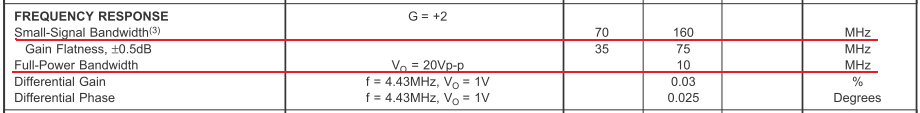
I agree with the statement in the first part. But the second part is wrong. GBW is measured in small-signal mode and it can be 7 ... 30 times more than the full power bandwidth. It is FPBW that is responsible for performance and is related to SR by the well-known formula:
SR = 2π fVp
Attachments
We should define what we mean by fast!
Bruno was addressing the incorrect assumption made by many people that amplifiers with a low open loop BW ( eg like an opamp) of just a few Hz were ‘slow’ which of course is not correct.
If you take an amplifier with an OLG of say 140 dB (eg an LM4562) and a -3dB OLBW of 3 Hz and a UGF of 55 MHz, when you close the loop at say 20 dB gain, the closed loop BW is 5.5 MHz. This is not a slow amplifier.
You are talking of course about slew rate in your post.
I usually quote slew rate, full output rise time like 150 V/ us from +-90% of the rails (good one for CFA because they usually don’t have a slew rate mechanism like a VFA) and then small signal time - I measure that at 1-2 V pk- pk output (small signal)
On rail to rail rise time it’s typically 500-700 ns and small signal 30-50 ns.
Your simulations look ridiculous. For some reason, you are trying to contrast the value of SR with Bruno's theses. It is assumed that the value must be appropriate. You are not trying to work with transistors in the TO-92 case on a load of 2 Ohms with an amplitude of 80V peak-to-peak, right? So why do you lower the SR to small values and try to prove something? All your examples are deliberately made by lame horses. Rather, you show ignorance of the issue under discussion.SR and its relationship with the type of amplifier correction
Bonsai, you can make sure that even with BW = 13 MHz the amplifier is slow
And in addition, I want to ask what amps with deep NFB you heard and what was the depth of loop gain at 20 kHz for comparison? Were they really performed technically correctly? You don't seem to know what you're talking about. This is exactly what Bruno said: "10. Make sure that you have actually heard an amplifier with a large loop gain before giving your opinion on deep feedback."
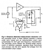
The hearing mechanism has an integration time which seems to be forgotten in the discusion. It is at least 1000 times longer than 25 ns.I was also convinced as you that the quality of amp depends upon the delay. I will found my posts advising composite amp designer in that direction. This is the LM3886 with gain of 2.8, delay 25ns.
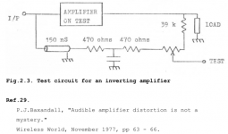
Some years ago, I tried to measure the propagation delay of a standard amplifier using square waves. I looked a the foot of the signal. I found it was far shorter than 100 ns (the amplifier you quote has nothing exceptionnal from this point of view) but the result appears to me as being ridiculous because what can only be visually considered as the start of the signal is its emergence from the noise.amplifier, which has a tPD less than 100 ns.
Last edited:
give oscillograms of what you measured, if you can. And it’s not clear what it’s about ...Some years ago, I tried to measure the propagation delay of a standard amplifier using square waves. I looked a the foot of the signal. I found it was far shorter than 100 ns (the amplifier you quote has nothing exceptionnal from this point of view) but the result appears to me as being ridiculous because what can only be visually considered as the start of the signal is its emergence from the noise.
It would be better that you repeat the same experience yourself to evaluate the propagation time in an amplifier. You just need a signal generator and an oscilloscope. I did it about ten years ago. My conclusion was that it is not an issue.give oscillograms of what you measured, if you can. And it’s not clear what it’s about ...
In a data sheet around 1978, Nelson Pass published propagation delays of some Treshold amplification circuits. They were less than 100 ns.
You should take more interest in the data of ear integration time.
many of the conclusions at the end of the article are highly controversial. For example this one:
«Open-loop bandwidth is no measure of how fast an amplifier is. Gain-bandwidth product is. »
It is only controversial for those who did not understand the explanation of why this is so.
Jan
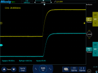
after the revision, the delay time was reduced from 360 ns to 90 ns and the sound quality improved markedly. Information for those who understand sound.Nice transient. And how does this relate to audibility?
It is only controversial for those who did not understand the explanation of why this is so.
Jan
I kind of lucidly explained that slew rate is related to the FPBW, and not to GBW. It's strange that you don't know simple truths.
Petr
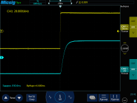
after the revision, the delay time was reduced from 360 ns to 90 ns and the sound quality improved markedly. Information for those who understand sound.
So anecdote. The plural of which doggedy refuses to be data.
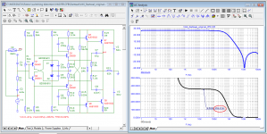
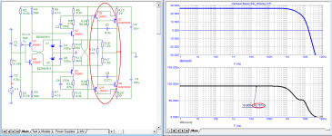
And what do we see on the waveform? The instrument automatically measured the latency on the level of the middle pulse. Can this be considered a delay time at all? The output signal must enter some kind of tolerance tube. Only then can we assume that we received a signal at the output. Open the video amplifier Datasheet for an example and you will see an entry like " setup time to 0.01%" - this will be correct. Multiply your numbers by 5-6 times. And this is still optimistic.here is an example of measuring the propagation delay time in a real amplifier and in a virtual one
- Home
- Amplifiers
- Solid State
- First cycle distortion - Graham, what is that?