I will try to answer this question
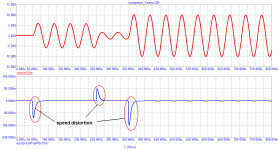
The problem with the signal that you describe in the .pdf is that again it is a start of a sinewave that starts infinitely fast. The reason that you only see it in the 1st cycle is because that 1st cycle is completely artificial and not a real life signal*. The answer is staring you in the face there: after that 1st artificial start, there is no speed distortion anywhere else, only a pure delay.
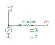
If you want to do it correctly, send the sine wave input signal through a low pass of say 30kHz (to stay with the DIM30). Then run your sim and use the output of the low pass as the input signal and check the distortion against that. You will not find 'speed distortion', because now you work with real life signals and the amp can handle that fine*.
The only thing you will see is a delay as you show in your .pdf after the 1st cycle.
BTW, No chance for Graham to answer your question. He died many years ago.
Jan
* That is also the reason that a distortion simulation looks at the signal after the initial start-up, because that 1st cycle, being a simulation artefact, would give wrong results. It is an artefact because the simulated signal source starts infinitely fast.
**Just as the amp can handle musical transients, which also do not start infinitely fast; a musical instrument is a mechanical instrument and instrument vibrations do not start and stop infinitely fast. Even electronic music does not stop and start infinitely fast, it has a time to grow, sustain, and die out.
what kind of amplifier? give a diagram
best regards
Petr
Any standard audio amplifier has a loop transit time of 10’s of ns. This is not the same thing as phase shift (a property of all reactive circuits)
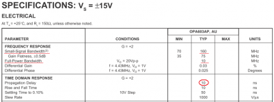
You mean that any standard amplifier has the same parameters as this high-speed op-amp (FPBW, SR). The time Propagation Delay (tPD) is indicated for a gain of + -1. With increasing gain, the tPD also increases.Any standard audio amplifier has a loop transit time of 10’s of ns. This is not the same thing as phase shift (a property of all reactive circuits)
Attachments
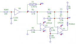
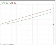
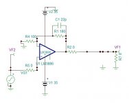
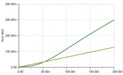
The scheme and test results are shown in the figures. I have already explained, I repeat again: no filtering does not save an amplifier with a long signal propagation delay. Note the amplitude and duration of velocity distortions. Their duration is commensurate with half the useful signal period. At the same time, there is no distortion in the steady state! Straight line, zero distortion.If you want to do it correctly, send the sine wave input signal through a low pass of say 30kHz (to stay with the DIM30). Then run your sim and use the output of the low pass as the input signal and check the distortion against that. You will not find 'speed distortion', because now you work with real life signals and the amp can handle that fine*.
The only thing you will see is a delay as you show in your .pdf after the 1st cycle.
regards
Petr
Attachments
This is the transient response of a low pass RC. Should it be considered as FCD?
In opamp and miller compensated amplifiers, the open loop F response is only few hertz may be a khz. When the transient reaches the output it arrives as -90° phase shift. The feedback will bring to the final phase shift, but in how long time? The input to adjust the phase needs an error voltage to charge the miller capacitor, mean while the output gets the same kind distortion as the crossover but only at the beginning the burst as piano note. I call this the blindness of an amplifier and it is the difference of the low pass transient and that of the amplifier. If the music is just few instruments playing each individual notes, no problem, if it is a choral or large orchestra , you can hear clearly the distortion. The music that I use since more that half century is the "Happy together" of the Turtles, most difficult ones are requiems of Verdi and Mozart.
Attachments
small addition:
A significant influence on the determination of such parameters of sound as pitch, timbre, etc., is exerted by the temporal behavior of the first five to seven harmonics, as well as a number of "non-expanded" harmonics up to the 15th ... 18th. ... in real musical instruments, rather complex signals are created with a large number of overtones, a certain inharmony between them, a complex dynamic development in time of their spectral and temporal envelope, and a certain dynamics of changes in phase relationships, to which the hearing aid is quite sensitive. It was found that hearing responds primarily to the rate of phase change (ie, its frequency derivative), which is called the "group delay time" [2]. If we consider that the highest notes of musical instruments are at frequencies of about 8 kHz, then even the 5th harmonic will be at a frequency of 40 kHz.
Something about this issue is clarified by the article [3].
Literature:
1. I.Dostal, Operational Amplifiers, 1982
2. И.Алдошина, Тембр, часть 2, "Звукорежиссер", 2001, №3
3. James Boyk, There's Life Above 20 Kilohertz!
A Survey of Musical Instrument Spectra to 102.4 Khz, There's life above 20 kilohertz! A survey of musical instrument spectra to 102.4 kHz
So what you are saying is there is a delay between the input signal and the feedback signal and this causes ‘speed’ distortion because the amplifier feedback loop overshoots during this time?
You are heading into dangerous territory. This stuff (see below) and similar has been debunked by some seriously good engineers/academics:-
A Future Without Feedback? | Stereophile.com
The ‘speed’ distortion is perfectly explainable and is not some new mechanism. You minimize this type of loop overshoot by compensating the amplifier correctly and ensuring the loop BW is adequate. If these things aren’t right then that’s because of bad design.
An easier way to test for this is to feed a very fast rise time square wave into the amp and then look at the LTP output current. There will be an overshoot time and magnitude which you can measure and minimize through compensation and input stage degeneration.
Last edited:
Well, judge for yourself. You have brought a low-pass filter with a cutoff frequency of 160 kHz and having a group delay of 1 μs. I have already sharpened my attention several times: the most important parameter in the amplifier is the time Propagation Delay, which should be no more than 50 ... 70 ns. If you put such a filter at the input of the amplifier, can you get the total group delay as needed? Of course not. It is no coincidence that I gave the parameters of the Goldmund Telos 5000 amplifier, which has a tPD less than 100 ns. Nevertheless, despite the astronomical cost, this is far from the best amplifier in terms of sound quality.This is the transient response of a low pass RC. Should it be considered as FCD?
What is the danger in your opinion if you design amplifiers with a group delay not more than 50 ... 70 ns?You are heading into dangerous territory.
"the most important parameter in the amplifier is the time Propagation Delay, which should be no more than 50 ... 70 ns. "
Where do you get this from?
From my own experience and analysis of the best amplifiers for sound quality
Last edited:
Is Pavel's listening test relevant to this discussion? https://www.diyaudio.com/forums/eve...difference-2-solid-preamps-2.html#post5966475
https://www.diyaudio.com/forums/eve...ifference-2-solid-preamps-38.html#post5996607
https://www.diyaudio.com/forums/eve...ifference-2-solid-preamps-38.html#post5996607
Last edited:
I was also convinced as you that the quality of amp depends upon the delay. I will found my posts advising composite amp designer in that direction. This is the LM3886 with gain of 2.8, delay 25nsWell, judge for yourself. You have brought a low-pass filter with a cutoff frequency of 160 kHz and having a group delay of 1 μs. I have already sharpened my attention several times: the most important parameter in the amplifier is the time Propagation Delay, which should be no more than 50 ... 70 ns. If you put such a filter at the input of the amplifier, can you get the total group delay as needed? Of course not. It is no coincidence that I gave the parameters of the Goldmund Telos 5000 amplifier, which has a tPD less than 100 ns. Nevertheless, despite the astronomical cost, this is far from the best amplifier in terms of sound quality.
I have another amplifier posted that has 10ns and is my best sounding amp superior to SET 300b. But , I did notice if tube amps don't have this defect in sound, because their open loop response covers all the spectrum, by this the feedback doesn't need to adjust the phase. In other words if you have an opamp or power amp with open loop response over 20khz , JLH 30khz, you don't need to get concerned about this type of distortion.
Attachments
what do you mean by rubbish? Please write this listN101N: long list of conceptual rubbish
otherwise it sounds like an insult
There are no scientifically conducted and peer reviewed tests that link ‘perceived’ sound quality with amplifier group delay that I am ware of other than the stuff used in the 1970’s to set for example the DIN GD spec which had nothing to do with amplifiers ( the DIN spec set 25 milli-seconds as the limit of audibility at LF).
It was explained to you what it is that’s causing what you call ‘time distortion’. It is the amplifiers loop behavior and quite explainable in terms of feedback and loop propagation delay.
It’s no good simply repeating what you believe in the hope it will convince skeptics. You have to show hard evidence and proof. Otherwise, it is simply conjecture.
Last edited:
- Home
- Amplifiers
- Solid State
- First cycle distortion - Graham, what is that?