Whenever you get an asymmetric music signal the "DC average" (which is really not D.C) is a rolling average which will cause capacitors to charge and discharge slightly. As has been well known for years.
In any amplifier with capacitor coupling somewhere, this will exist to a certain degree. I would suggest that a fully D.C. power amplifier will not suffer the same effect.
Many amplifiers have an input capacitor and a feedback decoupling capacitor. For each capacitor in the path there will be an n-1 zero crossing to a transient, or, "music signal with moving D.C. average" to try to phrase this.
Early amplifiers with output capacitors of 2mF had a poor bass response. The "resonance" of more than one capacitor can cause an audible signal if the time constants are high enough. But usually, they are not (2mF tended to be a common exception at the time).
Therefore, "first cycle distortion" singles out the charge/discharge of capacitors which could arise anywhere. If the frequency of any low frequency "bounce" is inaudible, by making the time constants large, is it a problem?
Last edited:
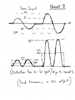
Earlier amplifiers with coupling capacitors often had higher levels of 2nd harmonic. From previous dialog it was shown that the 2nd harmonic is intimately connected of proportionality to a DC component. What you refer to as "music signal with moving D.C. average" seems equivalent to what I would phrase as "modulation distortion". In the distortion figure below there is shown two amplitudes of 2nd harmonic with a proportionate DC shift. It can be realized that any number of DC shifts can exist as corresponding to any number of sine input amplitudes.
This is one step away from modulating the input sine wave by changing the amplitudes prior to DC. settling, causing what you describe as a moving D.C. average before DC settling occurs. This is why the distortion you describe can alternatively be identified as modulation distortion, for reasons that the nonlinearity as a moving D.C. can be generated from the modulation of the input sine.
This moving D.C. generated by amplitude modulation is a signal that can appear of reality above the low frequency cutoff point, this as a function of the sine modulation frequency being high enough to support its appearance. If this is then coupled out using capacitors it stores or "memorizes" this moving DC as causing phase shifting. In other words artificial bass is generated, that unlike linear bass, seems of potential a masking artifact preventing clear bass (as good bass), to be realized.
Attachments
Linsley-Hood who worked in the lab of a capacitor manufacturer wrote a series of three articles "Audio Amplifier Design, Engineering or Alchemy" in Everyday with Practical Electronics magazine - issues August, September, and October 1993.
The September issue covered capacitors where he noted that all capacitors have some element of parasitic resistance in series with the capacitance which he labelled Rx described as being a long way from being an ideal resistor and its' value is likely to be voltage, temperature, polarity, and frequency dependent as well as being influenced by the shape of the voltage of the a.c. waveform being applied to it.
Rx he said in relation to R in a negative feedback RC arm decoupling to earth would be a significant fraction of R+Rx and will have an effect on the gain of an amplifier. With an electrolytic for C the effect would be so small on THD measured at say 1kHz. If, however inter-modulation effects produced when an amplifier is driven by several simultaneous input signals is tracked down using a spectrum analyser to find the spurious signals which have been generated, the differences between one blocking capacitor and another would be more easily seen.
"Changing the type of capacitor used in this position does indeed affect sound quality which is what IMD measurements will point out, especially if one of the signals used in the test is of square-wave type"
Yes, in audio design there are a lot of 2nd order effects, large signal effects, etc., that are difficult to model accurately. Not only that but if the system is good enough it becomes audibly obvious that burn-in effects are also occurring. The only way I know of to get to a superior sounding audio design which also measures well is to start prototyping, listening, and measuring. It helps a lot to have low distortion speakers in a treated room, just like it helps to have high quality bench test equipment. The point is that eventually one must leave simulation and move on.
I'm not sure that the description of a bass signal above the cut-off is really a good one. If we take the (poor, but illustrative) example of a typical 1970's design with input capacitor, feedback decoupling capacitor and output capacitor, three time constants will generate a combined low frequency roll-off which can be determined from the individual time constants considered more or less independent.
Take a typical set of time constants: perhaps an input capacitor of 1uF, with a 10k biasing resistor (-3dB=15.9Hz, perhaps pessimistically high) a feedback decoupling capacitor of 220uF with 47 ohm decoupling resistor (and a feedback resistor of say1.5k), and a 2.2mF output capacitor, the -3dB points being 15Hz and 9Hz) the combined -3dB point is about 26Hz. This does not even handle a 1mS pulse (square wave single) well, and reveals a high level of a (heavily damped) oscillation following the pulse. The following "bounce" crosses the zero line twice, discounting the first crossing on the down edge of the pulse which is a result of the RC droop.
But that trailing "bounce" is best described by the exponential time decay constants. Superficially it seems like a sinewave (heavily damped) with a frequency of about the same as the LF roll-off, but as I mentioned, the exponential nature of the RC circuit extends the response which may account for your "higher than LF roll-off" description.
The point I would make is that this is largely a consequence of the AC coupling, and well described by the response of RC coupled circuits to a signal, not a new distortion mechanism as it has been like that since, well, the first RC circuit was put together.
It does, however, explain the poor bass response of those early amplifiers, whatever input signal is applied and distortions added by the amplifier. Or, taking mjona's point, the distortions of older capacitors with (realtively) high ESR and ESL, which may be non-linear, but that is somewhat separate to the fundamental of RC time constants.
Last edited:
Yes, in audio design there are a lot of 2nd order effects, large signal effects, etc., that are difficult to model accurately. Not only that but if the system is good enough it becomes audibly obvious that burn-in effects are also occurring. The only way I know of to get to a superior sounding audio design which also measures well is to start prototyping, listening, and measuring. It helps a lot to have low distortion speakers in a treated room, just like it helps to have high quality bench test equipment. The point is that eventually one must leave simulation and move on.
Mark,
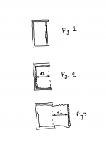
I’d first like to admit that my mind goes off track faster than a teenager seeing his first hooker. Please excuse the graphics, the intent was to be succinct. Speaking of speakers in relation to the 2nd harmonic, consider a closed box “air-suspension” speaker shown in figure 1 below. This is shown from the side, being considered having a rectangular flat piston that takes up the entirety of the front face. If we then apply a symmetric sine force of sufficient amplitude, and the speaker is not affected by variant internal pressure, the displacement extremes could take the positions indicated in Fig. 2 going inward and Fig. 3 going outward. In other words the speaker is of symmetric displacement.
If the internal pressure is taken into account, under circumstances the displacement is still that of Fig. 2 and Fig. 3, the inward pressure rises to infinity (as the enclosure volume reduces toward zero) and the outward pressure reduces to 1/2 going outward. The conclusion is that pressures are a-symmetric inside a closed box, as thereupon generating 2nd harmonic. What also occurs is that for any input sine signal that is fixed, there also exists a fixed displacement of the speaker diaphragm for each input level, as likely of proportionality to the amplitude of the 2nd harmonic. With the exception of leakage, closed box systems have no equivalency of high pass filtering. This includes under circumstances that the input is capacitively coupled. Hence modulation distortion (or inter-modulation distortion) generates components down to DC as physical displacement errors for any form of input stimulus.
Notwithstanding that such analysis is indeed correct I have been experimenting with creating leakages in cabinets, those being tuned psycho-acoustically. As you can imagine, (and seem likely to have personal experiences) there is always a difficulty in what is concluded correct or incorrect, or being perceived of improvement. It is always difficult to rule out distortions as existing unknown, and that the improvement is one of negating such distortion with another.
Gerrit
Attachments
I'm not sure that the description of a bass signal above the cut-off is really a good one.
It is important to isolate as many variables as possible to increase the probability of correctly understanding a particular phenomenon.
Capacitors affects are also personally concluded of considerable importance in effecting the quality of overall performance, contributing in terms of "memory" in a linear way in terms of R/C time constants, in linear and non-linear ways in terms of dielectric absorption, and in the memory of DC non-linear distortion generated by non-linear transfer functions. My focus is on the later, as notwithstanding affects that can be more dominant under circumstances you have presented.
It is considered that bass frequencies signals being generated from non-linear transfer curves by the modulation of a sine can have some equivalency of value being determined from IMD testing. For some, IMD testing is questionable, whereupon the question becomes as to "where is the second frequency" in musical reproduction that would cause it have importance. In musical reproduction signals can be considered as often highly modulated. Hence distortion values determined by a modulation method supports the conclusion that such testing can be important, even though both are.
Gerrit,
Not a fan of vented boxes, bass reflex, and or of passive radiators. If using box speakers I would rather sacrifice efficiency in exchange for more accurate LF transient response. That means a preference for sealed boxes of sturdy construction. Surely there are some others who would agree.
Not a fan of vented boxes, bass reflex, and or of passive radiators. If using box speakers I would rather sacrifice efficiency in exchange for more accurate LF transient response. That means a preference for sealed boxes of sturdy construction. Surely there are some others who would agree.
I agree in that vented boxes, bass reflex, etc., create bass as a function of damped resonance and hence can't deal with transients, however that isn't really what was meant.
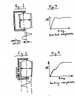
Fig. 1 shows the results of non-symmetric pressure, that for small boxes it can be realized increases in severity for a given SPL more quickly than a larger box. However if the boxed is "leaked" the buildup of pressure at lower frequency is released, resulting in returning the position back to the origin. It can be considered a mechanical way of capacitive coupling at low frequencies.
Fig. 3 shows a normal frequency graph for a ported design. Figure 4 shows what is expected happens for a leaky enclosure. Although transient response would still be affected this is balanced off by reducing the negative effects of non-linear pressure.
It is also considered that ports on many well respected speakers are smaller than would produce a response as deleterious as Fig. 3 indicates.
Attachments
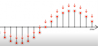
Come on Petr, you know this waveform is nonsense. You have connected samples with straight vertical and horizontal lines, and that is completely artificial, the signal does not look like this.
Run it through a band limiting filter or an ADC anti-aliasing filter like in the real world.
Don't try to prove something with stuff that doesn't exist.
I will give you the benefit of the doubt and assume that this is a result of your not knowing and not a deliberate misleading.
Jan
I counted the changes in 1 ms on Petr’s waveform. Definitely 44 plus a small one in a millisecond. Standard sampling frequency 44100 Hz. R-2R DACs produce such waveforms if their output is not smoothed out by a capacitor that degrades sound quality.
You don't get it either, do you? Starting out with a perfectly reasonable technical statement, then conclude it by some nonsense.
The fantastic music signal that comes out so great from that fantastic amp of yours must have gone through 100's of caps.
But of course, adding one more will totally destroy the sound.
Does nobody think anymore?
Please join Petr_2009.
Jan
D/A and A/D | Digital Show and Tell (Monty Montgomery @ xiph.org) - YouTube
Last edited:
You don't get it either, do you? Starting out with a perfectly reasonable technical statement, then conclude it by some nonsense.
The fantastic music signal that comes out so great from that fantastic amp of yours must have gone through 100's of caps.
But of course, adding one more will totally destroy the sound.
Does nobody think anymore?
Please join Petr_2009.
Jan
Please don't exaggerate, Jan!
Certainly the signal did not go through hundreds of capacitors. Adding one more will not destroy totally the sound of course but will degrade a little unnecessarily.
I mostly listen to natural dynamic range music from the 70s and 80s. In these times, electrolytic capacitors were much larger in size. These larger capacitors did not cause as much error in the signal as the current smaller components. The transistors weren't had so unnecessarily high gain, and maybe that's why they sounded better with their worse C-E to B-E thermal coupling.
Nowadays, better than 0.001% THD and harmonics below -110dB dazzles those who are unable to take a simple comparative listening test in practice but hunt for ultralow harmonics, while harmonics cannot be heard 60dB below the fundamental because of human ear masking effects. IMD cannot be heard below 0.01%.
Good luck with bettering the sound of amplifiers based on these easy to do but futile measurements!
(15..20 years ago I was one of those who measured THD and IMD of circuits. Was able to measure down to 3ppm, -110dB. Fortunately, I quit on time.
 )
)Mr. Kolinummi's book is on my desk since a week. It's no question that it's a good book. The memory distortion was given a very small part in the book. There is no real measurement on almost any topic. I see a lot of simulations and constant sine wave measurements using Audio Precision. Forgetting to mention the JFET cascoded JFET CCS is a pretty big mistake!
Mr. Kolinummi only reduced memory distorton after many in the audition test(!) felt the bass was thin on the first amp. So the measurements did not predict that some problem would be heard on the hearing test! Otherwise, he would have already made the second version of the amplifier. On the improved version some of the listeners missed warmness.
Natural, warm sound is the result of low memory distortion. By really eliminating these distortions will your amplifier sound warm! And this is not because of higher 2nd harmonic! You can add 2nd harmonic to your signal in a waveform editor but the music will not sound warmer or more natural because the amplifier still distorts.
I have measured internal voltages many times within an amplifier circuit. The output of the amplifiers does not show the internal initial thermal fault, which often reaches up to 10% even with cascoded circuits. Reducing the internal memory error will lead to a better sounding amplifier. Peufeu's Memory Distortion Philosophies page is a good starting point. He was to optimistic in his simulations. The real world is worse. Of course everything is good and nice while you (a general subject, not you, Jan) measure IMD and THD. But never listen, because it will be a confusing experience!
We really need to develop and standardize memory measurement for audio devices to end these exhausting fruitless debates. Once we know numerically the amount of memory distortion in each circuit, it is already possible to perform listening tests involving many people and then do correlation analysis on the data for determinig audibility.
Jan,
Petr in his attached waveform shows 44100Hz, but no one took the effort to count it. Someone even described it as definitely not a true sound sample. Yet it is, and all CDs are like that. That's why 44.1kHz is not enough for high quality sound.
Here is one of the songs I realy like for e.g.. One of the best hungarian female vocalist from 80's: Katona Klári - Egyszer volt
Things get complicated from 4:32 where the beautiful synth sound starts.
(Sharing a lossless FLAC would probably be infringing.)
Krisztian
Last edited:
I counted the changes in 1 ms on Petr’s waveform. Definitely 44 plus a small one in a millisecond. Standard sampling frequency 44100 Hz. R-2R DACs produce such waveforms if their output is not smoothed out by a capacitor that degrades sound quality.
This is incorrect. Such a waveform exists only in NOS dacs without any output filtering. I would think there are not many who would enjoy listening to such.
"In these times, electrolytic capacitors were much larger in size. These larger capacitors did not cause as much error in the signal as the current smaller components. The transistors weren't had so unnecessarily high gain, and maybe that's why they sounded better with their worse C-E to B-E thermal coupling."
Somewhat dubious statements.
Physically larger capacitors could distort through non-linear responses and Cyril Bateman demonstrated quite surprising distortions in capacitors he tested in 2002.
Capacitors have got physically smaller but electrically larger in the same size can. ESL and ESR has generally been reduced too, with a probable reduction in non-linear distortion. Are you suggesting that modern capacitors are now less linear than older ones?
As for your transistor comment, the junctions are all in the same piece of silicon. I presume you mean that a wider base in those older transistors has a greater thermal lag compared with a narrower base. I very much doubt that that gave better sound, and I suspect that the thermal conduction across the base is a small quantity given that most of the heat extracted is through the collector, in the opposite direction to the emitter.
Perhaps you have some data linking thermal impedances to sound quality?
I don't disagree that thermal tracking may be important in terms of a transient distortion, but claims like that without data are suspect.
This is incorrect. Such a waveform exists only in NOS dacs without any output filtering. I would think there are not many who would enjoy listening to such.
They have no idea what aliasing is. They think the filter is to smooth the 'stair steps', which aren't there to begin with. It's called a reconstruction filter.
I've posted the link to the YouTube that explains it twice now, but some can't learn even if their life depended on it.
The samples are discrete time samples, like:
time 1 - value 1
time 2 - value 2
etc.
There are no stair steps, it's an artifact of the graphing!
Jan
Attachments
Last edited:
Capacitors have got physically smaller but electrically larger in the same size can. ESL and ESR has generally been reduced too, with a probable reduction in non-linear distortion. Are you suggesting that modern capacitors are now less linear than older ones?
I'm suggesting that possibly mechanical resonances increased, robustness decreased through with the change.
Perhaps you have some data linking thermal impedances to sound quality?
I don't disagree that thermal tracking may be important in terms of a transient distortion, but claims like that without data are suspect.
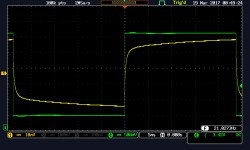
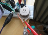
I measured 11 types of NPN transistors with a 21.03Hz square wave 4 years ago. I measured the termal error and the thermal cut-off frequency. The thing stopped then because I did not make the measuring circuit going down to DC voltage and so the data obtained is not necessarily accurate. It had a 0.035Hz filter in it. I implemented it on a test panel. Since then, I’ve been designing a PCB for it with offset adjustment. During the measurements at that time, I looked at the transistors with a current of 5mA connected as a constant current generator, and the C-E voltage varied between about 20 and 45 volts. Clearly, the OnSemi BC550C was the worst with its very high thermal cut-off frequency of 3kHz. The Toshiba SC2240 and OnSemi MPSA06 have an average of 1kHz. According to many reports, and to my ears, the 2SC2240 sounds better than the BC550. In the attached image, green is the C-E voltage (actually not 500mV/div but 5V/div) and yellow is the DUT emitter. (It's really 20mV/div) I could not measure the thermal cut-off frequency of the 2N3055 with the circuit at the time. It's clearly below 100Hz.
Attachments
They have no idea what aliasing is. They think the filter is to smooth the 'stair steps', which aren't there to begin with. It's called a reconstruction filter. Jan
'We' know very well what aliasing is. It's only exists because of inadequate sampling frequency. Probably at 384kHz there's no more need for an aliasing filter.
There is no aliasing on the vinyl record.
The effect of aliasing has nothing to do with sample rate, it always occurs , with 44.1kHz as well as 384kHz. Unless you take measures.
Please review it. Look up 'spectrum folding' for example.
You also missed the criticism about those waveforms. Nobody doubted that there are 44,100 samples in a second. The issue was something else.
Which you would have understood if you would have taken the trouble to check out that YouTube I posted.
Jan
Last edited:
This might help a few folks ‘Tom Kite Busts a Few Audio Myths’
AudioMyths[1]
The funniest one is ‘Vinyl is, like, 40 bits resolution’
Noise, bandwidth, resolution, IMD . . . All good fun!
AudioMyths[1]
The funniest one is ‘Vinyl is, like, 40 bits resolution’
Noise, bandwidth, resolution, IMD . . . All good fun!
Krisztian - thank you for your explanation. Thermal effects are indeed real and interesting to measure. What is missing is a correlation between the device thermal behaviour and distortion measurements in an amplifier. For example, is the difference between the BC550C result and the C2240 due to a worse Early effect (the C2240 being 120V rated compared to the BC550 60V)? (I have not checked the Early voltage on these devices myself BTW, but SPICE data indicates fairly low VAF values for the BC while the datasheet characteristics of the C2240 look better) Is the BC550/C2240 being used as a VAS or an input device with more or less constant collector voltage?
With modern amplifier design, having large open loop gain, the effects at frequencies below your "thermal cut off" points are going to be well corrected by negative feedback, and at higher frequencies the reduced OLG is not so important as thermal effects lag.
With modern amplifier design, having large open loop gain, the effects at frequencies below your "thermal cut off" points are going to be well corrected by negative feedback, and at higher frequencies the reduced OLG is not so important as thermal effects lag.
- Home
- Amplifiers
- Solid State
- First cycle distortion - Graham, what is that?