As I wrote: VCE varies with the absolute value of a 50Hz sine. So yes a half sine cycle of 50Hz is 10ms hence 5+5ms for a loop up and down. You have 100 half sine cycle in a second when its frequency is 50Hz.
No need for the emphasis in your response!
I took "loop up and down" to mean one complete (10ms) cycle.
It's obvious that rectified sinewave will give you the absolute value. If you're being so pedantic your PNP transistor should have been stated as Vce= the negative of the absolute value.
Does the looping reduce if you mount your BC560 on a heatsink ?
I didn't really understand the second sentence. I think even in one sine cycle especially for lower frequencies the positive and negative excursions pull back and forth the bias point a little because of thermal variations like on my OnSemi BC550 curve tracer photo: https://www.diyaudio.com/forums/att...-comments-thermal-distortion-bc560c-semi_-jpg
On the photo, VCE varies with the absolute value of a 50Hz sine. So each loop starting from the bottom left corner is a half sine along the horizontal axis. Each loop up and down is 5ms. The BC550 clearly easily tracks the self-dissipation induced thermal variations. VCE varies and so does the current gain. (The vertical axis is IC).
Krisztian
Fully agree, my 2nd sentence was only to highlight that it is the thermal cycling that causes it, and as you mentioned at the double frequency because it is due to absolute value that causes thermal variation.
All nicely described (and fixed) by Arto Kolinumi.
Arto designed amplifier stages where the thermal distortion was all but eliminated.
Jan
Another question I'm curious to the answers about:
How a 1kHz input signal can (even continuously) produce a higher frequency harmonics, "signals"?
Can someone give a concrete practical example how it's produced?
For example taking a specific part/circuit in transient mode explaining it during a few period of the sine wave?
Is this an example good enough?
Attachments
Another question I'm curious to the answers about:
How a 1kHz input signal can (even continuously) produce a higher frequency harmonics, "signals"?
Can someone give a concrete practical example how it's produced?
For example taking a specific part/circuit in transient mode explaining it during a few period of the sine wave?
The gain of the amplifier during the signal cycle is not constant, but varies with the signal level. For instance, with 1V signal the gain can be 10, and with 5V it can be 10.01, and with 10V it can be 9.97. It can also be different for positive and negative signals.
The result of this is that the output is not an exact copy of the input (only changed in level). It is changed in shape, the peaks may be a little lower or higher than the input signal.
Mr. Fourier has discovered that you can take apart that not-exact-the-same output as a combination of an exact copy of the input, plus (or minus) another signal, added/subtracted from it. This is the distortion, and it consists of normally quite small signals with frequencies which are an integer multiple of the input frequency. See attachment, courtesy Guido Tent of Tentlabs and Grimm Audio.
It's easy to see that the level and distribution of those harmonics depend on how that output wave deviates from an exact copy of the input signal.
Does that help?
Jan
Attachments
Last edited:
I find it curious how someone can dream up grand theories about FCD without even understanding what distortion is and how it is created.
Let alone the intricacies of settling time and such. Amazing.
Maybe I am too old to understand such a mindset.
Jan
Honestly, I also do not understand how a voltage amplifier can be developed by subscribing to the theory of distortion compensation, which in reality does not work. I mean your amplifier from AudioXpress. A simple voltage amplifier without GNFB presented by Hawxford performs several orders of magnitude better in all respects, including no FCD distortion and speed distortion.
Perhaps you are really too old to understand the meaning of FCD and other concepts.
One thing is abundantly clear and fundamentally important to me is that you are honest in conveying what you believe true. What I find tiresome is wasting my time listening to those who, with my undeniable confidence, are blatantly dishonest. With that said please do not take things I say and that can be counter to what you believe true, in any way as an affront to your honesty and integrity. There isn't anything wrong with continuing to defend your position if challenged.
Thanks to Hierfi for the support, it gave me confidence in my rightness.
Honestly, I also do not understand how a voltage amplifier can be developed by subscribing to the theory of distortion compensation, which in reality does not work. I mean your amplifier from AudioXpress. A simple voltage amplifier without GNFB presented by Hawxford performs several orders of magnitude better in all respects, including no FCD distortion and speed distortion.
Perhaps you are really too old to understand the meaning of FCD and other concepts.
Ohh yes, that amplifier is not the worlds 'best, I agree. In fact it was designed with a specific experiment in mind. That's why it is called 'paX'- power amplifier eXperimental.
Did you read the purpose of the design exercise? I can send you the article if you wish.
Jan
Please excuse the poor quality sketching below. It was produced on a "reMarkable 2" pad that my daughter gave me as a gift. Nice girl... more than I deserve.
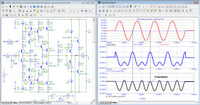
Hierfi, you showed the measurement results for the 3rd harmonic when it is in phase with the fundamental.
Consider the measurement of distortions by the Hafler method on a model of an amplifier made on ideal components with artificially introduced nonlinearity in the form of the 3rd harmonic. The third harmonic can be either in phase with the fundamental harmonic or in antiphase. Let's consider both options. If the fundamental harmonic is undercompensated, there will be a residual level of the undercompensated fundamental harmonic in the distortion products.
Everything is signed in the figures.
Attachments
What is undercompensated fundamental harmonic? Do you mean a part of the fundamental that is not nulled out by the subtraction?
Yes, in that case we'll see some fundamental in the output (difference) signal. But it is not part of the distortion, of course.
Or is there another point you want to make? Should you not make a better subtractor to null the fundamental completely, with a lead capacitor or something?
Jan
Yes, in that case we'll see some fundamental in the output (difference) signal. But it is not part of the distortion, of course.
Or is there another point you want to make? Should you not make a better subtractor to null the fundamental completely, with a lead capacitor or something?
Jan
Last edited:
Has this thread lost track?
If I take a step back ...
To answer the question on distortion Jan pointed out that harmonics over the base frequency of a continuous sinewave arises through a non-linearity in the response of an amplifier.
Those harmonics can be determined from a Fourier analysis which is usually carried out by a fast Fourier transform algorithm.
In theory combining those harmonics will lead to reconstructing the original signal, thereby demonstrating that they are indeed components of the original.
But often the FFT results are plotted as amplitude only. The reconstructed wave can look quite different from the original if the phases of the harmonics are not considered, which has been correctly pointed out. You have to go a step further than just reporting the amplitude to obtain the phases.
When it comes to music this is a different situation. Music is not a continuum of sinewaves, but a series of sounds which are made up from waveforms that start and stop, with varying frequencies of course, and with varying attack and decay characteristics on perhaps any of the harmonics.
These cannot be expressed in terms of a Fourier series of signals, but as an integral of a frequency function (if wanting the time dependency) or vice versa. That integral extends from potentially - infinity to + infinity, but the point is that it contains, essentially, frequency components that extend a long way out: a pulsed sinewave of one, or ten, cycles is not by any means a single fixed frequency.
THerefore, passing a signal which contains high frequency components (even if not expressed as a series but an integral) through a bandwidth limited amplifier is going to cut the higher frequency components out. So the perceived sound will depend on the bandwidth; and to a first order an amplifier can be considered as an RC filter which will give a first-order indication of the output.
That has driven the need for a high bandwidth in hifi amplifiers, but there seems to be a general agreement that something in the region of 200kHz is adequate for most listeners.
On top of that, any capacitor or inductor will change the nature of the signal. For example, older amplifiers with coupling capacitors, typically 2mF in the old days, had a poor LF response where the phase shifts create a voltage which is not present in the input. This isn't a harmonic distortion but can be seen in a simple CR network equivalent, to a first order. It is particularly shown up in that a 20Hz cut-off (-3dB), which used to be a target, has a lousy square wave response at 20Hz, thus causing some bass to sound "thin" or "weak".
So it seems to me that "first cycle distortion" is an unfortunate term which confuses essentially a response of a finite bandwidth limited system to what would be an "infinite" signal source with actual harmonic distortion.
Though many if not all music signals are filtered in any case, making the need for power amplifiers over about 200kHz less necessary, and the low frequency artifacts can be ameliorated by using big feedback decoupling capacitors - or even extending the response to D.C. (which I tend to do as that avoids "capacitor distortion" in the main!).
Last edited:
Thanks to Hierfi for the support, it gave me confidence in my rightness.
I think you misinterpreted the comment and saw it as a support for your stance when in fact it might be the other way around.
//
Petr-1951 sees evidence of his rightness everywhere, but he is deaf to the facts that refute his theory and does not even consider the possibility of the fallacy of his judgments. This explains the haste in sorting through various sources in search of arguments - collecting as many authoritative or pseudo-authoritative opinions as possible, directly or indirectly testifying in his support.I think you misinterpreted the comment and saw it as a support for your stance when in fact it might be the other way around.
//
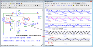
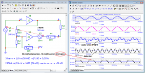
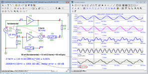
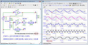
With overcompensation (Ku (tPD) = 20.05 of the delayed input signal is greater than the nominal (20.00)), the error waveforms will be mirrored to those that occurred with undercompensation (Ku (tPD) = 19.95)
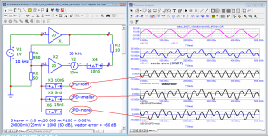
completely zeroed fundamental signal on the 4th chart out of 5
completely zeroed fundamental signal on the 4th chart out of 5
Attachments
Last edited:
Has this thread lost track?
If I take a step back ...
To answer the question on distortion Jan pointed out that harmonics over the base frequency of a continuous sinewave arises through a non-linearity in the response of an amplifier.
Those harmonics can be determined from a Fourier analysis which is usually carried out by a fast Fourier transform algorithm.
In theory combining those harmonics will lead to reconstructing the original signal, thereby demonstrating that they are indeed components of the original.
But often the FFT results are plotted as amplitude only. The reconstructed wave can look quite different from the original if the phases of the harmonics are not considered, which has been correctly pointed out. You have to go a step further than just reporting the amplitude to obtain the phases.
When it comes to music this is a different situation. Music is not a continuum of sinewaves, but a series of sounds which are made up from waveforms that start and stop, with varying frequencies of course, and with varying attack and decay characteristics on perhaps any of the harmonics.
These cannot be expressed in terms of a Fourier series of signals, but as an integral of a frequency function (if wanting the time dependency) or vice versa. That integral extends from potentially - infinity to + infinity, but the point is that it contains, essentially, frequency components that extend a long way out: a pulsed sinewave of one, or ten, cycles is not by any means a single fixed frequency.
THerefore, passing a signal which contains high frequency components (even if not expressed as a series but an integral) through a bandwidth limited amplifier is going to cut the higher frequency components out. So the perceived sound will depend on the bandwidth; and to a first order an amplifier can be considered as an RC filter which will give a first-order indication of the output.
That has driven the need for a high bandwidth in hifi amplifiers, but there seems to be a general agreement that something in the region of 200kHz is adequate for most listeners.
On top of that, any capacitor or inductor will change the nature of the signal. For example, older amplifiers with coupling capacitors, typically 2mF in the old days, had a poor LF response where the phase shifts create a voltage which is not present in the input. This isn't a harmonic distortion but can be seen in a simple CR network equivalent, to a first order. It is particularly shown up in that a 20Hz cut-off (-3dB), which used to be a target, has a lousy square wave response at 20Hz, thus causing some bass to sound "thin" or "weak".
So it seems to me that "first cycle distortion" is an unfortunate term which confuses essentially a response of a finite bandwidth limited system to what would be an "infinite" signal source with actual harmonic distortion.
Though many if not all music signals are filtered in any case, making the need for power amplifiers over about 200kHz less necessary, and the low frequency artifacts can be ameliorated by using big feedback decoupling capacitors - or even extending the response to D.C. (which I tend to do as that avoids "capacitor distortion" in the main!).
Good summary John. But you lost me when you said 'that has driven the need for a high bandwidth in hifi amplifiers,', I couldn't find what has done that.
As far as I can see, requirements for 200kHz bandwidth are driven by specmanship and commercial motives ("Mine is faster than yours") rather than design motives.
Jan
With overcompensation (Ku (tPD) = 20.05 of the delayed input signal is greater than the nominal (20.00)), the error waveforms will be mirrored to those that occurred with undercompensation (Ku (tPD) = 19.95)
completely zeroed fundamental signal on the 4th chart out of 5
I *think* what you say here, is that when the fundamental is not nulled out, a small residual level will be shown in the output of the difference network.
The distortion will be shown also of course and added to this residual, and it will depend on the phase of the distortion how the resulting waveform will look.
Yes?
In that case I agree.
Jan
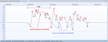
Let's take a fragment of a music signal from any editor and see what it is.
As we can see here nothing resembles a sinusoid, even its half-cycle.
I highlighted the zero crossing points with the highest slew rate in blue; these are the places where crossover distortions are likely to appear.
I highlighted places of abrupt changes in dV/dt in red - these are places where speed distortions may appear.
As you can see, there are many times more places highlighted in red than in blue.
And if crossover distortions are clearly noticeable by ear in a number of class AB amplifiers, then speed distortions will be perfectly audible even in class A amplifiers, if measures are not taken to minimize them.
According to Hafler's ideas, the signal propagation delay time should not exceed 10 ns, only in this case we will get vector errors at a frequency of 10 kHz -60 dB. In what Hafler's mistake I have already shown on XL-280 tests.
Attachments
- Home
- Amplifiers
- Solid State
- First cycle distortion - Graham, what is that?