... As long as there's no real effort by people who can clearly hear these imperfections in an amplifier to use measurements and try to correlate the heard with the measured parameters there will be no path forward...
So long a proprietary research conceals much of new practical knowledge, you shouldn't expect to get measurements new to you for free.
I am just stating that if phase is a difference between voltage and current being separated in time by a reactive element like a capacitor or a inductor, then in the example above there will be a 4 ms delay between when the feedback loop would need to control the output stage and when the feedback loop actually manages to control the output stage.
Yet reality shows us that there is continuous control. If reality doesn't conform to your view, should we declare reality as wrong?
Jan
The arguments so far don't seem to be accomplishing much.
People often hear real effects, then make up incorrect theories in an attempt at explanation. Human nature at work.
In this thread the only thing half the people care about is that above all else theory must remain unpolluted.
The other guy just needs some help figuring out the set of real reasons why lots of amplifiers sound better if they pass a stress test than if they don't.
Both sides are only concerned with their own issues.
So long a proprietary research conceals much of new practical knowledge, you shouldn't expect to get measurements new to you for free.
I heard the "for free" argument several times from you now. Do you have something useful to share, share it freely. Otherwise vague comments are pretty much useless.
On your last comment: If we want to enable people with less hearing experience to build better gear we have to come up with better measurement tools and procedures. If that's not the goal I'll shut up. If that's the goal, well let's do it. I don't regard myself as having golden ears though, so I'm not qualified for the hearing part. So other people will have to step in.
Seems to me that there is a huge discrepany though. People known to tune their gear by ear refuse to help to develop good measurement tools but continue to look down on those that don't have these uber-qualified ears and have to rely on measurements. We're stuck forever.
The arguments so far don't seem to be accomplishing much.
People often hear real effects, then make up incorrect theories in an attempt at explanation. Human nature at work.
In this thread the only thing half the people care about is that above all else theory must remain unpolluted.
The other guy just needs some help figuring out the set of real reasons why lots of amplifiers sound better if they pass a stress test than if they don't.
Both sides are only concerned with their own issues.
If theory is allowed to be "polluted" (modified) then there are two possibilities:
1. correlate measurements and hearing experience, deduct a new theory and proof it by further measurements
2. come up with a new theory in your head and proof it with measurements
Se how there's no way around actual measurements to proof a theory, otherwise it's just a thought experiment and of no real value to people developing circuits to sound better and verifying their improvements.

Your model does show something quite different once we start increasing the phase shift by increasing the order of the filter.
It seems like the whole filtered wave does not only lean heavily but starts and stops (or crosses the zero line if you prefer) with a distinct delay with the green square wave (input) as a reference.
The pink line is "out4" and the blue line is "out1".
People often hear real effects
How often is that proven though? People 'say' they hear real effects or 'think' they hear real effects. There is no evidence presented to back that up before the mad theories appear.
Have you been talking to Joe Rasmussen?I am not inventing anything. I am pretty certain that "Volt X Current = power" is something someone has come up with before me... I am just stating that if phase is a difference between voltage and current being separated in time by a reactive element like a capacitor or a inductor, then in the example above there will be a 4 ms delay between when the feedback loop would need to control the output stage and when the feedback loop actually manages to control the output stage.
If there is no delay in energy in the LTSpice example above, what does the 4 ms in the simulated graph show? Why is the green curve still at -1 volt when the blue curve is at a full +1 volt? Is this not a lag of energy?
People have problems when they have invested much in alternative views.Yet reality shows us that there is continuous control. If reality doesn't conform to your view, should we declare reality as wrong?
View attachment 900132
Your model does show something quite different once we start increasing the phase shift by increasing the order of the filter.
It seems like the whole filtered wave does not only lean heavily but starts and stops (or crosses the zero line if you prefer) with a distinct delay with the green square wave (input) as a reference.
The pink line is "out4" and the blue line is "out1".
You should show the difference between each input and output. The input for out4 is out3.
And I have already mentioned a transit delay, which is minuscule compared to the apparent 'delay' of the phase shift.
But I am not interested further in this. I gave the pointers, up to you what you do with it. Best of luck.
Jan
The arguments so far don't seem to be accomplishing much.
People often hear real effects, then make up incorrect theories in an attempt at explanation. Human nature at work.
In this thread the only thing half the people care about is that above all else theory must remain unpolluted.
The other guy just needs some help figuring out the set of real reasons why lots of amplifiers sound better if they pass a stress test than if they don't.
Both sides are only concerned with their own issues.
Do you honestly think one can isolate the aspect that are discussed in a listening test? First cycle, which seem to be just really a tiny part of the first cycle, and nothing else?
//
People have problems when they have invested much in alternative views.
I very much know the feeling. Many years ago I thought I had invented something that for sure was going to make me rich & famous.
I was wrong, but it took many smart people enormous time to get it into my head. No way I was going to give up the idea that would make me famous!
Without realizing I constructed all kinds of circular and flawed reasonings in a desperate effort to save myself.
It was a sobering but highly educative experience.
Jan
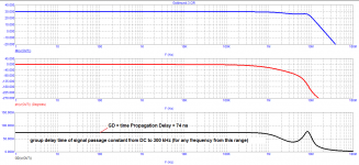
Here is the Bode plot of the younger Goldmund-3 model.
tPD = 74 ns from DC to 300 kHz
Dear opponents, finally understand the difference between phase shift (second graph) and time Propagation Delay (3 graph). In DC amplifiers, the signal propagation delay time is physically equal to GD. The older model is more powerful, but the parameters are similar, see figure
Attachments
So in response we get other mad theories that people must be hallucinating what they hear. Mad theories on both sides.
I would say that bias has been well investigated and documented. Until you can show that bias has been removed the onus is on the person claiming the audibility. OR they can give some measurements.
Here is the Bode plot of the younger Goldmund-3 model.
tPD = 74 ns from DC to 300 kHz
Dear opponents, finally understand the difference between phase shift (second graph) and time Propagation Delay (3 graph). In DC amplifiers, the signal propagation delay time is physically equal to GD. The older model is more powerful, but the parameters are similar, see figure
We already understand the difference. For a linear, time invariant system (like all audio amplifiers) the group delay is minus the derivative of the phase shift. The group delay can be made asymptotically equal to the propagation delay, but only for an all pass filter. There is no DC propagation delay or group delay, these concepts make no sense at DC.
Please stop trolling.
Have you been talking to Joe Rasmussen?
Who is he?
I have not been talking with anyone. I post here once in a while, and that is probably the only communication I have with people that like to develop amplifiers.
Do you honestly think one can isolate the aspect that are discussed in a listening test? First cycle, which seem to be just really a tiny part of the first cycle, and nothing else?
Since music is very little sine waves or complexes of sine waves and more about transient signals with decay (often consisting of something superficially resembling sine waves), "first cycle distortion" seems to be something that effects most of the reproduced music.
Once you move away from traditional NFB amps and start to use Feed Forward Error Correction instead you open up a whole new level of performance. But no steady state measurement of sine waves across a non inductive resistor will show you why.
 .
.- Home
- Amplifiers
- Solid State
- First cycle distortion - Graham, what is that?