You assume they are aware of their expectations and their perceptions. They're not.
Jan
I'm confused
") Let's imagine they expected to hear a difference but didn't? Regards their perceptions, I'm presuming rapid switching so they don't forget
Let's imagine they expected to hear a difference but didn't? Regards their perceptions, I'm presuming rapid switching so they don't forget Some may have a different idea of what rapid is in this context. Without the electronic switcher, <1/2 sec. switch time is not feasible and doesn't maintain the objectivity of test.rapid switching
The so called "speed error" seems to be of normal, typical behavior of any servo system, a behavioral property one would anticipate a negative feedback amplifier to possess. Why would anyone be surprised with it and bother even giving it a term? In a bandwidth limited negative feedback system, literarily any input signal related error is a "speed error".
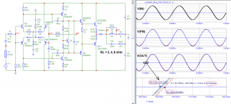
In fact you can predict that behavior easily from a loop gain plot that decays over frequency typical of a feedback amplifier. At the beginning of the abrupt emerging train of sine wave there is a lot of higher frequency components, or harmonics, in the spectrum, where less loop gain than at lower frequencies is available to suppress distortion, hence the "spike" of errors. After that moment, the high frequency component diminishes, and input spectrum narrows down to a single peak at 200Hz base tone, and the error is then determined by the loop gain at 200Hz alone.
In a typical feedback amplifier having an open loop bandwidth at 20 Hz, the loop gain begins to decay at 20 Hz over frequency. We can quite confidently predict such an amplifier will present lowest error at 20Hz and lower frequencies, and errors going higher with frequency past 20Hz. Shall we then call the error at 200Hz "speed distortion" too, because it is higher than what it is at 20Hz? Shall we call all distortions at all frequencies higher than 20Hz "speed distortion" as well?
As far as I know, the feedback amp behavior described as the so called "speed distortion" or "speed error" has long been sorted out, and it has not changed before or after the collapse of USSR.
A CD is an bandwidth limited system so no, it doesn't happen. Think of an infinitely fast impulse, that has a spectrum DC to light. Using it as an audio source you must run it through a bandwidth limited system, and you loose all that HF junk, and what remains is a slowly starting and stopping signal, fit to test an audio amp.
The completely artificial signal with infinitely fast starting and stopping sine waves is a nonsensical way to test an amp.
People often have completely wrong ideas of 'an audio transient'. Ann audio transient produced by an instrument is in reality quite slow.
Jan
The completely artificial signal with infinitely fast starting and stopping sine waves is a nonsensical way to test an amp.
People often have completely wrong ideas of 'an audio transient'. Ann audio transient produced by an instrument is in reality quite slow.
Jan
No one replied to this but I see that we are still circuling around this:
As I understand, Graham also just said that this could be an analyzing method in simulators to magnify a specific amplifier
behaviour and in addition he also stated that based on his experience it's correlates with his subjective sense of audio quality.
So it's not about real life music signals.
It's like hitting a steady (not moving) bell with a big hammer and checking for the initial (very first) transient response.
(Instead of analysing the bell's performance in the middle of the normal ringing process.)
PS: Petrov: I wrote you a PM, pls check, thx!
First cycle test
Sorry I couldn't find: was there an original article about this concept?
Anyways I'd guess the point is to test a system after it
reached its steady state (without signal at the input)
and then apply only one cycle, as this method can be more relevant
regarding transient behaviour as a conventional test with continous
repetitive sine waves or even square waves.
Maybe this method helps to magnify the behaviour to random changes which
can be relevant even with real life music signal as it is also "random".
What if there is some "distortion overshoot" kind of problem
at the very first change which then "settles" to the 10th period?
What if the change of distortion in time is one of the most
annoying factor to our ears?
Square wave vs real life signal
I never understood why this method is controversial based on
the concept that real life music doesn't have such waveforms.
It's just a technical method for development and testing purposes.
Of course it's a much cruel drive but thats how we can zoom in
to some transient glitches in the amplification process.
As I understand, Graham also just said that this could be an analyzing method in simulators to magnify a specific amplifier
behaviour and in addition he also stated that based on his experience it's correlates with his subjective sense of audio quality.
So it's not about real life music signals.
It's like hitting a steady (not moving) bell with a big hammer and checking for the initial (very first) transient response.
(Instead of analysing the bell's performance in the middle of the normal ringing process.)
PS: Petrov: I wrote you a PM, pls check, thx!
But what has this to do with music?
All sound is sine waves.
Sledgehammer Week - The Slow Mo Guys - YouTube
Slow Motion Punch in the Stomach - The Slow Mo Guys - YouTube
All stress test is based on this fundamental truth.
Out of the comfort zone testing...
Slow Motion Punch in the Stomach - The Slow Mo Guys - YouTube
Yeah but some times you can analyze something much better with an extraordinary input.All sound is sine waves.
All stress test is based on this fundamental truth.
Out of the comfort zone testing...
Yeah but some times you can analyze something much better with an extraordinary input.
All stress test is based on this fundamental truth.
Out of the comfort zone testing...
To be honest I am big in testing out of comfort zone, A sudden train of sine wave is way too comfortable. A square wave is better but limited. I even designed and built my own uncomfortable signal generator to do it.
BUBBA-JAG-GENERATOR
By the way I have a few Bubba-Jag PCB to give away if anyone is interested.
Yeah, this is also a good example for a special test which brings up some intresting details as described here in the PDF: Bubba-Jag
I guess we have to seek for more and more alternative testing methods like this and the FCD.
Maybe one (or all of them together) can lead us to a much better understanding of sound quality.
BTW: great work, nice PCB design! ;-)
I guess we have to seek for more and more alternative testing methods like this and the FCD.
Maybe one (or all of them together) can lead us to a much better understanding of sound quality.
BTW: great work, nice PCB design! ;-)
Stress test signals aren't actually needed, unless you are designing by trial and error. Phase and gain margin are predictors of behavior. The weakness is models, not the concept.
petr_2009 seems happy with 60 degrees phase margin. Others are not. At 90 degrees, negative feedback has no benefit and is detrimental at lower values. Therefore, some believe that phase margin should never fall below 90 degrees within the entire bandwidth, which better preserves servo behavior. First is to determine use case environment. Then optimizing servo behavior seems a sensible approach since slew rate, THD and load tolerance performance are balanced. These are all contributors to sound quality.
I don't see that Graham performed these engineering evaluations.
A designer may opt to maximize slew rate and sacrifice load tolerance and stability. That is their prerogative..
Last edited:
All sound is sine waves
Very few instruments produce linear sinusoidal wave shapes.
How can all sounds be sinewaves?
Musical instruments are often thought of as linear harmonic systems, and a first-order description of their operation can indeed be given on this basis, once we recognise a few inharmonic exceptions such as drums and bells. A closer examination, however, shows that the reality is very different from this. Sustained-tone instruments, such as violins, flutes and trumpets, have resonators that are only approximately harmonic, and their operation and harmonic sound spectrum both rely upon the extreme nonlinearity of their driving mechanisms. Such instruments might be described as `essentially nonlinear'. In impulsively excited instruments, such as pianos, guitars, gongs and cymbals, however, the nonlinearity is `incidental', although it may produce striking aural results, including transitions to chaotic behaviour. This paper reviews the basic physics of a wide variety of musical instruments and investigates the role of nonlinearity in their operation.
From: The nonlinear physics of musical instruments - IOPscience
But be well aware what the stress test actually tells you. You can run a car into a concrete block to stress test the crumpling zone, but what does it tell you about how well the car drives on your daily commute? Nothing at all.
Jan
on our daily journeys, we do not drive our car on exceptionally smooth surfaces like ice on a lake. Therefore, driving on ice also does not tell us how the car will behave on a bumpy road.
regards
Petr
- Home
- Amplifiers
- Solid State
- First cycle distortion - Graham, what is that?