In the mid-1980s, I was preparing a portable cassette recorder for mass production. The question was how to make the output power amplifier? The cheapest option was the use of ready-made amplifiers in a microcircuit version of the TDA type. But it turned out that the full power bandwidth (FPBW) of these microcircuits does not exceed 45 ... 50 kHz and the sound of such amplifiers is "dead", "dull", "not transparent" ...
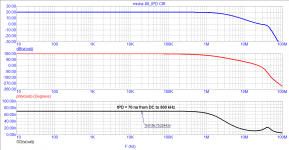
I had to stop at a Russian-made microcircuit with external correction circuits. According to the typical connection scheme, the FPBW was also 50 kHz. After experiments with correction circuits, it was possible to expand the full power band to 450 kHz. To ensure the technological headroom, the FPBW was reduced to 350 kHz. Only with this version of the amplifier, the tape recorder sounded as desired and began to differ favorably in sound from tape recorders of a similar class.
I had to stop at a Russian-made microcircuit with external correction circuits. According to the typical connection scheme, the FPBW was also 50 kHz. After experiments with correction circuits, it was possible to expand the full power band to 450 kHz. To ensure the technological headroom, the FPBW was reduced to 350 kHz. Only with this version of the amplifier, the tape recorder sounded as desired and began to differ favorably in sound from tape recorders of a similar class.
The cheapest option was the use of ready-made amplifiers in a microcircuit version of the TDA type. But it turned out that the full power bandwidth (FPBW) of these microcircuits does not exceed 45 ... 50 kHz and the sound of such amplifiers is "dead", "dull", "not transparent" ...
Why are you sure the FPBW was the culprit for bad sound? There are many things that could cause bad sound.
AFAIK there are plenty of highly regarded amplifiers with similar FPBW.
You are arguing that only the full power bandwidth and slew rate produced good sound, forgetting that it also increased the depth of feedback. The rate of increase should be appropriate to the task, but it will not be enough for lunch)) Enough to isolate the parameters and attribute all the merits to one or the other.... I had to stop at a Russian-made microcircuit with external correction circuits. According to the typical connection scheme, the FPBW was also 50 kHz. After experiments with correction circuits, it was possible to expand the full power band to 450 kHz. To ensure the technological headroom, the FPBW was reduced to 350 kHz. Only with this version of the amplifier, the tape recorder sounded as desired and began to differ favorably in sound from tape recorders of a similar class.
I think this amplifier was not developed in vain
Was the scheme published? If so, where can you find it?First cycle distortion - Graham, what is that?
jan.didden
I have build Winfield Hill's 10MHz 100W amp. Pretty heroic effort, but doable.
Some authors argue that TIM distortion does not exist, they say these are ordinary nonlinear distortions. In my opinion, TIM distortion is a dynamic distortion associated with a specific limitation of the slew rate of the output voltage
Now find some music that will stress any reasonable power amplifier? The original Otala papers used a mistracking MC cartridge to come up with a transient even that was then jumped upon as proof of a new distortion to deal with. I would have got a better cartridge myself. In the digital age no music exists with these sorts of transients so where is the problem to solve?
In the mid-1980s, I was preparing a portable cassette recorder for mass production.
Casettes had a bias frequency of between 40kHz and 105kHz on a quick search.
So by amplifying all the noise, crud, HF bias etc you got a different sound from a well engineered product? Well colour me suprised...After experiments with correction circuits, it was possible to expand the full power band to 450 kHz. To ensure the technological headroom, the FPBW was reduced to 350 kHz. Only with this version of the amplifier, the tape recorder sounded as desired and began to differ favorably in sound from tape recorders of a similar class.
In the mid-1980s, I was preparing a portable cassette recorder for mass production. The question was how to make the output power amplifier? The cheapest option was the use of ready-made amplifiers in a microcircuit version of the TDA type. But it turned out that the full power bandwidth (FPBW) of these microcircuits does not exceed 45 ... 50 kHz and the sound of such amplifiers is "dead", "dull", "not transparent" ...
I had to stop at a Russian-made microcircuit with external correction circuits. According to the typical connection scheme, the FPBW was also 50 kHz. After experiments with correction circuits, it was possible to expand the full power band to 450 kHz. To ensure the technological headroom, the FPBW was reduced to 350 kHz. Only with this version of the amplifier, the tape recorder sounded as desired and began to differ favorably in sound from tape recorders of a similar class.
For a cassette with 15khz BW? Waste of time.
Yes, today there are few who understand, but still there are. It's a pity that Graham was beaten to death ...In the days people still understood what they were talking about we'd do an impulse response measurement and then went to lunch.
Jan
Anyone who understands sound and circuitry (understands the nuances in the work of amplifiers) today develops these amplifiers:
???? ?? ????????? ????? ???????? "??????????" ?????????
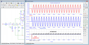
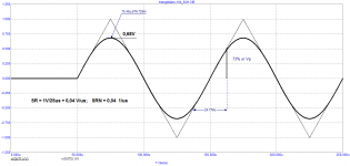
As can be seen from the oscillograms on the stationary signal in the steady state, there are no speed distortions, there are only nonlinear and crossover distortions and speed distortions only at the beginning of the first period (FCD).
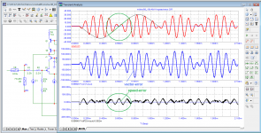
It is enough to modulate the signal and distortions immediately appear. The highest rate distortion is in the middle of the 1 kHz baseband signal, where the modulation rate is highest. And although at this point the amplitude of the 10 kHz signal is minimal, the rate distortion is maximal. And this is on the simplest signal. Here is an explanation of why microdynamics is disturbed in amplifiers with a long signal propagation delay time, high-frequency signals of small amplitude are clogged with speed distortions.
Attachments
the real sound signal is much more complicated, if of course you understand anything about it ...So you are simulating an impossible signal. so what?
If you understand so well, then explain how the carrier frequency abruptly changed the phase in the opposite direction. What linear circuit can pass such a signal through itself without distorting it?the real sound signal is much more complicated, if of course you understand anything about it ...
In addition, our ear also has its own inertia described by bandpass filters when constructing equivalent equivalent circuits. Do you think such a crazy signal is able to reach the neurons in their original form?
You are using the term "velocity distortion" from the book by Jiri Dostal, but you did not bother to read it carefully. For example, the author conducts an analysis with consideration of the input-output voltage delta (velocity, vector and phase errors). But it is not clear why you grabbed them, because we only listen to the output signal without reference to the input signal. We can only be interested in the derivative of these parameters. However, in the linear mode of the circuit, it is negligible and appears only when excited with a step signal, which you so skillfully disguise under the guise of various ingenious test signals. But the essence is the same - a latent step effect with piecewise signal approximation.
If you understand so well, then explain how the carrier frequency abruptly changed the phase in the opposite direction. What linear circuit can pass such a signal through itself without distorting it?
In addition, our ear also has its own inertia described by bandpass filters when constructing equivalent equivalent circuits. Do you think such a crazy signal is able to reach the neurons in their original form?
You are using the term "velocity distortion" from the book by Jiri Dostal, but you did not bother to read it carefully. For example, the author conducts an analysis with consideration of the input-output voltage delta (velocity, vector and phase errors). But it is not clear why you grabbed them, because we only listen to the output signal without reference to the input signal. We can only be interested in the derivative of these parameters. However, in the linear mode of the circuit, it is negligible and appears only when excited with a step signal, which you so skillfully disguise under the guise of various ingenious test signals. But the essence is the same - a latent step effect with piecewise signal approximation.
A long due voice of sanity.
Some authors argue that TIM distortion does not exist
Maybe you could point to some that think that TIM distortion don't exist?
Most importentingly:
Please use a real output stage in your simulations instead of a R.
If you dont understand the difference, please let us know.
Stein
I re-read some of Graham's posts, while I wasted a lot of time reading empty posts of numerous trolls ...
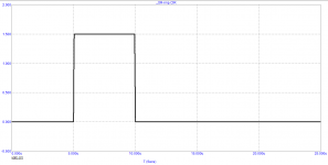
If I understood correctly, Graham was surprised: why a suddenly starting pulse can be used to measure RT and SR, but to check the quality of the gain of the first period, it is impossible to apply a suddenly starting sinusoidal signal with a frequency of 10 kHz.
After all, if you take a typical amplifier for home use, then its peak output voltage usually does not exceed 30 Volts, and the slew rate is about 0.8 V / μs, which is "tough" even for the "slowest" amplifier (the slew rate of the triangular signal and that less - only 0.6 V / μs). Graham suggested only to measure the parameters of the first period and check how these parameters correlate with the sound quality of amplifiers. Instead, they began to ascribe to Graham that he does not understand anything in theory, they say there is nothing to watch linear distortions. In response, Graham revised the 600 pages from 1980 in New York and did not find such a term as linear distortion, he found only the term linearity, which is not the same thing.
Best regards
Petr
Attachments
some quotes from Graham's posts:
“I am not trying to lecture other readers who are already learned and well experienced, but I am here trying to illustrate why first cycle waveform examination has value because of the composite nature of a suddenly starting first sinewave cycle, that is missing with steady sine, and should not overcome an amplifier's slew rate, as with square wave. Ditto via reverse suddenly starting sine injection into the output terminal to observe amplifier NFB loop control in time.
To me 'linearity' has always been 'continuous proportionality'.
That is a fundamental definition that was not written by me...
Those who accept the term 'linear distortion', could be confused by that terminology in a manner that enables them to think there is 'linearity of amplitude response' where actually a fractional voltage amplitude error can exist within the time period of the composite waveform!
Amplifier amplitude linearity can be measured in time isolation to specify a good thd figure, and yet reproduction can still sound poor with dynamic waveforms because of the reactive delays associated with its internal stabilisation and NFB circuitry.
For those who don't deny its existence, this is where First Cycle Distortion observation will show on the simulator which amplifiers are capable of clean dynamic reproduction
If FCD "is just the normal" then why not study it?
I suggest that denying the use of first cycle observation is to deny insight into amplifier circuit operation.
Many solid-state amplifier designers would get a surprise if they set thd performance aside for just a moment and studied the first cycle (dynamic linearity) behaviour and output characteristics of their own creations.”
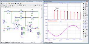
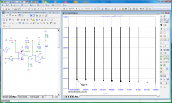
microcap software version 9 allows you to measure THD at any period. This feature is not available in older versions of the program.
However, in older versions of the program it is also possible to measure the spectrum of distortions in the first period. Let us check the distortions of the previously considered composite amplifier in the first period using MC9 and MC11.
“I am not trying to lecture other readers who are already learned and well experienced, but I am here trying to illustrate why first cycle waveform examination has value because of the composite nature of a suddenly starting first sinewave cycle, that is missing with steady sine, and should not overcome an amplifier's slew rate, as with square wave. Ditto via reverse suddenly starting sine injection into the output terminal to observe amplifier NFB loop control in time.
To me 'linearity' has always been 'continuous proportionality'.
That is a fundamental definition that was not written by me...
Those who accept the term 'linear distortion', could be confused by that terminology in a manner that enables them to think there is 'linearity of amplitude response' where actually a fractional voltage amplitude error can exist within the time period of the composite waveform!
Amplifier amplitude linearity can be measured in time isolation to specify a good thd figure, and yet reproduction can still sound poor with dynamic waveforms because of the reactive delays associated with its internal stabilisation and NFB circuitry.
For those who don't deny its existence, this is where First Cycle Distortion observation will show on the simulator which amplifiers are capable of clean dynamic reproduction
If FCD "is just the normal" then why not study it?
I suggest that denying the use of first cycle observation is to deny insight into amplifier circuit operation.
Many solid-state amplifier designers would get a surprise if they set thd performance aside for just a moment and studied the first cycle (dynamic linearity) behaviour and output characteristics of their own creations.”
microcap software version 9 allows you to measure THD at any period. This feature is not available in older versions of the program.
However, in older versions of the program it is also possible to measure the spectrum of distortions in the first period. Let us check the distortions of the previously considered composite amplifier in the first period using MC9 and MC11.
Attachments
Can't you really see the difference between sine and meander pitch? Isn't it clear to you that when the meander is filed, there is no question of the operating mode? The essence of this test is to overload the comparison unit with a differential voltage and study its response when overloading. What kind of quality assessment can we talk about in such a mode, if in the working cycle such a situation should be excluded and not take place?I re-read some of Graham's posts, while I wasted a lot of time reading empty posts of numerous trolls ...
If I understood correctly, Graham was surprised: why a suddenly starting pulse can be used to measure RT and SR, but to check the quality of the gain of the first period, it is impossible to apply a suddenly starting sinusoidal signal with a frequency of 10 kHz.
...
In response, Graham revised the 600 pages from 1980 in New York and did not find such a term as linear distortion, he found only the term linearity, which is not the same thing.
I don’t know where the late Graham was looking, but it’s easy to find a definition. Here are some examples:
"Linear distortion is a change in the waveform over time, caused by differences in the transmission conditions of its components. It is important to note here that these differences do not lead to new components of the transmitted signal" - Paul Skritek, Reference Manual for Audio Circuitry (1991)
"Distortions of a signal when passing through an amplifier, due to the dependence of the amplifier parameters on frequency and not depending on the amplitude of the input signal, are called linear distortions" - Gennady Korolev, Electronic devices of automation (1991)
"Due to the presence in the amplifier circuit of lumped and distributed capacitances and inductances, the gain of the amplifier changes with frequency, both in absolute value and in phase. As a result, individual harmonic components of the complex periodic oscillation applied to the input are amplified by the amplifier unequally and are shifted by them at different angles. . This leads to distortion of the shape of the amplified signals even if there are no non-linear elements in the amplifier circuits; therefore, such distortions are called linear. " - Tsykin, Electronic Amplifiers (1965)
P.S. Read the definition of trolling, you might then realize that this expression is not appropriate in this context.
- Home
- Amplifiers
- Solid State
- First cycle distortion - Graham, what is that?