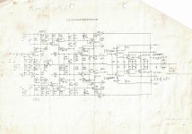
Gentlemen, sorry for bad old copy, see schematic attached.
This is a quasi famous "Class A" power amp, the origin is end of the seventies, made in Gemany : "Vernissage Kraft 100" (so you guess the output should be 100 watts per channel). Pictures can be seen when searching for the complete phrase.
This is one of the heaviest amps of its time, it has massive aluminium case and very strong heat sinks. Item with serial number 029 made 1982 was in my workshop last week.
On inspection the output is not what you would think, very strong distortion starts from a couple of watts, but with low voltages it is clean. The distortion looks like some strange combination of crossover and compression at the same time. I saw the same effect in unit no. 103 (made 1985?) in my workshop some 30 years ago. It is not form of a fault, but seems to be intrinsic to the design.
Looking at the output stage it is fairly conventional and can not be blamed I think. The driver stage, having some cascode complication should also work fine. I suspect the error to be in the input stage. This is fairly conventional also, again with some cascode complication and feedback goes to the emitters (no differential pairs). My first guess is biasing of the input stage is not correct and I would probably change V3, V4 to LEDs in order try to improve this.
Any suggestions are welcome. I am not into simulation, but perhaps somebody is interested to do this. After all this is kind of a thought experiment, the amp is repaired and works as it was, but for me the way of operation is insufficient to say the least and if I had plenty of time would probably see this as a challenge and not only thought exercise. Any work done to this amplifier is very cumbersome and time consuming.
Attachments
Last edited:
Lots of issues. Temped to go after the "over design, over complicated" bits.
1. I don't like the diodes on the emitter resistors, and these would start to conduct when driven as you describe.
2. I don't like the cascoded pre-drivers and C20,C21 may have failed.
3. The driver and pre-drivers should be cross-coupled and not tied to the output.
4. Whatever is in the collector of the drivers may have failed.
5. The cascoded Darlington VAS can oscillate by themselves, only saved by C6,C7.
6. Large ,low voltage caps like C4,C5 are prone to failure and if one were open then you would have one polarity signal path, no power in one direction. It might be worth replacing all the electrolytic caps.
7. There are a lot of wasted voltage drops and over-complicated bits, too many stages to put a feedback loop around. I would probably gut it in favor of a good A-B design like Self's blameless circuits using (some of) the same parts, and add current limit.
Last edited:
According to this site it was a school project.
Half a Million uF PSU & 80A bridge Double 1000VA transformers ??
No wonder it weights 50Kg.
http://www.vernissage-laboratorium.de/kraft-100/
Half a Million uF PSU & 80A bridge Double 1000VA transformers ??
No wonder it weights 50Kg.
http://www.vernissage-laboratorium.de/kraft-100/
Member
Joined 2009
Paid Member
According to this site it was a school project.
Half a Million uF PSU & 80A bridge Double 1000VA transformers ??
No wonder it weights 50Kg.
Kraft 100 | vernissage laboratorium
Do not confuse "Bauhaus" style with an ordinary school project ..
Who is addressed here ? Thanks.Not sure why you would bother when there are better options out there. If you like bipolar then consider the KRELL one which has a huge thread somewhere around here.
Member
Joined 2009
Paid Member
You - at least I thought you were looking to invest some time for better results. Unless this amp has sentimental value you might be better to reuse the box, power supply and other pricy parts to rebuild around a better amp design. The KSA50 could be a good option, with lots of information available.
I think it's cool enough to restore, or at least get it back to sounding something like it used to.
After that, i agree it does sound like lot of useful iron and casework + stuff to re-use for future projects. Imo, build a SissySIT.
If all else fails, i bet you could use the 1KVA cores as a decent boat-anchor")
After that, i agree it does sound like lot of useful iron and casework + stuff to re-use for future projects. Imo, build a SissySIT.
If all else fails, i bet you could use the 1KVA cores as a decent boat-anchor
Last edited:
- Status
- This old topic is closed. If you want to reopen this topic, contact a moderator using the "Report Post" button.
- Home
- Amplifiers
- Solid State
- Have a look at this power amp schematic