I found it - it was in ETI mag as part of his modular preamp in April 1992. It's here:
https://www.americanradiohistory.com/Archive-Electronics-Today/90s/Electronics-Today-1992-04.pdf
If you don't want to wade through that, here's the original schematic
https://www.americanradiohistory.com/Archive-Electronics-Today/90s/Electronics-Today-1992-04.pdf
If you don't want to wade through that, here's the original schematic
Attachments
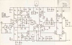
Yes the sensitivities should read ... 3.7mV (mm), 340uV (mc).
The gain numbers are correct .
I have recently encountered this in the thread started by... Anthony.taylor1967...( Gain resistors on JLH phono ) over in analogue source.
Just looked at the overload voltages and the typos persist they should read .... 67mV (mm) , 6mV (mc) .
Last edited:
Hello
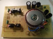
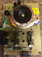
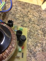
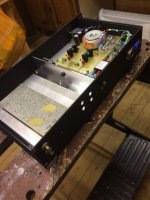
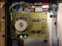
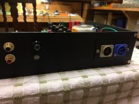
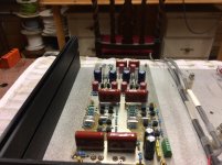
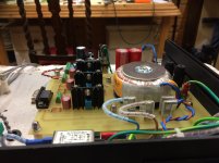
little update .. mounted the power transformer today onto the PCB, for some reason took me ages to find the best fit and configuration of fitment that I was happy with, I did not want loads of flying leads all over the place .... so on the whole am happy with this for now ..
little update .. mounted the power transformer today onto the PCB, for some reason took me ages to find the best fit and configuration of fitment that I was happy with, I did not want loads of flying leads all over the place .... so on the whole am happy with this for now ..
Attachments
Hello
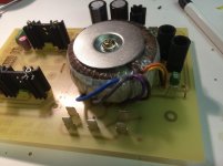
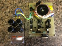
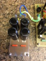
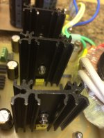
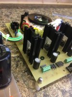
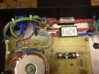
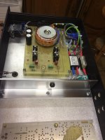
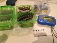
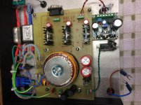
This was the psu I was going to use but was to big for the case .. so decided to put this on the shelf for the Class A head phone amplifier for a later date .. pics just for info
This was the psu I was going to use but was to big for the case .. so decided to put this on the shelf for the Class A head phone amplifier for a later date .. pics just for info
Attachments
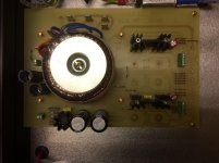
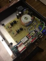
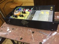
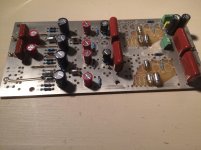
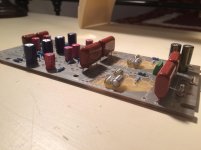
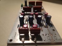
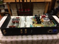
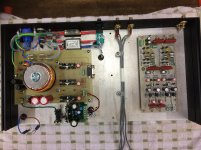
Hello quick update .. pcb's all mounted and PSU tested all OK
Attachments
Interesting.
I couldn't find any JLH pcbs so decided to make it my 'learning about KiCad' project and based on the schematic on Paul Kemble's site.
I've been trying to finish the PCB layout this week. At current rate of progress I might actually have something assembled early next year. Or later")
I couldn't find any JLH pcbs so decided to make it my 'learning about KiCad' project and based on the schematic on Paul Kemble's site.
I've been trying to finish the PCB layout this week. At current rate of progress I might actually have something assembled early next year. Or later
You have gerbers? I though all of that was lost when Hart closed. Did you manage to buy up all their remaining boards and docs?
I might be interested in a board, but only if my KiCad efforts crash and burn... Having got this far, I really want to try mine to see if it works. Planned to be powered by a silent switcher and a board per channel. Still thinking about component choices for some of the capacitors.
I'm also toying with a KiCad layout for an earlier design JLH did for HFN/RR. I'd intended to make it when the article was published but producing a board turned out to be too difficult. I still have the transistors I ordered at the time (1979) so I thought why not...
Hello Steven
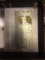
I have always been a fan of JLH and HART kits ... so have been purchasing their PCB's for years ... but when no longer available I made clones of all the PCB's with some minor improvements and made my own PCB's with updated Gerber files 99% same as the originals but with more robust PCB tracks and better connections etc
I have the whole range for my own use
- Home
- Source & Line
- Analogue Source
- JLH Shunt feedback phono amp construction