Double Die
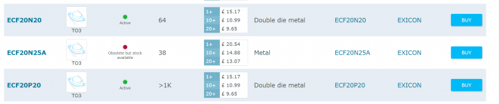
From the current Profusion site. Ordering shortly!
As I understand, the OP wants to use TO3 parts because the chassis already has provision for mounting them. That makes sense, rather than hacking the heatsink about, unless absolutely necessary.
The problem is that whilst Lateral mosfets are a sure-fire and simply applied device, the metal can varieties are close to un-obtanium presently. There was yet another thread here only week or so ago, moaning about general scarcity of lateral mosfets - check the recent threads if interested in the suggestions but I don't think you'll find much stock of genuine TO3 parts presently, let alone the double-die varieties.
From the current Profusion site. Ordering shortly!
Attachments
Rod's boards are for two pairs of TO3P latfets (flatpack plastic types), not for TO3! Here is the pic of my ESP P101 build.
ivan, can you tell me what is the clipping performance at 10KHz for this amp?
Keep in mind that in their application note Hitachi explicitly suggests that Laterals should be directly soldered to the PCB and to keep connection between output transistors and PCB as short as possible to prevent oscillation. What Tandberg did was not ideal and could be the source of troubles. I think that malfunction could have been caused by that unfortunate detail.
ivan, can you tell me what is the clipping performance at 10KHz for this amp?
I never tested it at clipping power because unfortunately I don't have that powerful 8 Ohm dummy load. I tested it at 4 Ohm dummy at lower powers and noticed some strange oscillation bursts but my build was with 68nF bypass caps instead of 100nF. When I desoldered 68nF and put 100nF that bursts disappeared. I think that 220nF would be even better. I built it in 2012 and used original Hitachi Latfets.
I must say that I always like the sound of amplifiers with one pair of outputs more than same amplifier with two or more output pairs. For P101 I used two pairs because I had a stock of Hitachi latfets but I think that it would be better if I used only one pair. I only build home amplifiers, never sound reinforcement amplifiers.
Last edited:
Keep in mind that in their application note Hitachi explicitly suggests that Laterals should be directly soldered to the PCB and to keep connection between output transistors and PCB as short as possible to prevent oscillation. What Tandberg did was not ideal and could be the source of troubles. I think that malfunction could have been caused by that unfortunate detail.
If you would read the posts carefully, you would see that I stated the amplifier section never failed in all the many years I used the Tandberg. The multi-wafer selector switch and other controls were the demise of the 3012 amp.
If you keep the wiring short, you should not have an issue.
I have built a few this way without problems. Bias adjusts fine and looks good on a scope. I think you are over-reacting a bit!
I never tested it at clipping power because unfortunately I don't have that powerful 8 Ohm dummy load..
you can test with no load, BRIEFLY! (the zobel R will disspate about 0.3W assuming 10R/0.1uF at 40Vpeak/10KHz sine.)
you can test with no load, BRIEFLY! (the zobel R will disspate about 0.3W assuming 10R/0.1uF at 40Vpeak/10KHz sine.)
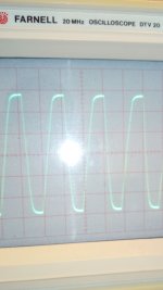
I used 4R dummy load at 10kHz. Here is the scope result. Not exactly what I expected. I expected nice flat line at the clipping.
Attachments
Tandberg P101 Progress
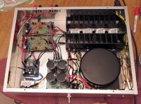
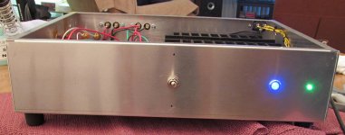
ESP P101 amp built from Tandberg 3012 transformer and heat sink assembly.
Barely Luke warm with 30mA bias. Sound is exceptionally clean.
Power light with standby and on condition. Light for speaker relay status.
Need to clean up the wiring a bit. More to come.
More to come
ESP P101 amp built from Tandberg 3012 transformer and heat sink assembly.
Barely Luke warm with 30mA bias. Sound is exceptionally clean.
Power light with standby and on condition. Light for speaker relay status.
Need to clean up the wiring a bit. More to come.
More to come
Attachments
P101 Build Relay Contact Issue
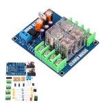
So I purchased and installed the pictured Ebay (Chinese) speaker Relay assembly with Omron G2R-2 relays. Dual relay contacts ea. rated at 5A or 10A per channel. The problem did not shown up due to high output failure but low level test tone level tests especially in the 80-100 Hz range. The sound became raspy and distorted like a dirty preamp monitor switch (both channels). If I turned up the volume, the symptoms cleared up. I verified that it was the relay contacts when I bypassed the relays with clip leads. Clean output.
Not sure if this is common issue with relays and low levels or if they are just faulty. Looking into other boards or options. Replace the current Omron relays or go with a different relay board with beefier relays?
Attachments
Relay contacts certainly give problems with low level audio but that's after many years, due to contamination from accumulated arcing debris, airborne dust, sulphation from automotive and industrial pollution etc. For new relays to have this problem, it says fake or bad quality control to me. G2R relays have been very popular for decades but they've been assembled in China and elsewhere in SE Asia for many years now and many design details have changed significantly. What you get now isn't the same as the original type used in so many high quality Japanese amplifiers up to 20 or so years ago.
The relays need to have a a high DC contact rating, at least 30V, to reduce the chance of the contacts welding together or suffering arcing damage when they try to open under a fault condition. Many cheap relays I've seen in recent times are obviously not suitable because the clearance and spring force isn't sufficient but we buy on price and low-res pics from Ebay stores which isn't a good way to buy anything that needs to perform reliably for safety, just sayin'.
I don't know if you have experimented with bias but 30mA is way too low for any power mosfet anyway. Early lateral mosfet DIY designs usually suffered from too low a bias current spec. and soon gained a bad rep for harsh sound. They were popular for stage and pro. applications where high power more or less obscured the distortion problem. 100mA bias current per output pair is recommended and typical of most class AB Mosfet audio amplifiers for home use.
57v rails seems high for single pair output AND 4 ohm load. I am using single pair of IRFp9140, 9240 at 40v and they seem to be fine. The LatFETS are tougher tho.
if you have a low open loop gain amplifier or a unstable design the bias current matters. If you have a stable, high bandwidth amplifier crossover components become visible under load when the bias is 2 -3 volts low at 20khz. I can't hear an obvious difference with the bias dropped from 7.8v ( 70ma) to 4.5v while playing music ( 1 -5 w) , it does show up on the scope. 0v still sounds good. It is one of the tests my amp must pass.
if you have a low open loop gain amplifier or a unstable design the bias current matters. If you have a stable, high bandwidth amplifier crossover components become visible under load when the bias is 2 -3 volts low at 20khz. I can't hear an obvious difference with the bias dropped from 7.8v ( 70ma) to 4.5v while playing music ( 1 -5 w) , it does show up on the scope. 0v still sounds good. It is one of the tests my amp must pass.
Last edited:
Ian Finch; I don't know if you have experimented with bias but 30mA is way too low for any power mosfet anyway. Early lateral mosfet DIY designs usually suffered from too low a bias current spec. and soon gained a bad rep for harsh sound. They were popular for stage and pro. applications where high power more or less obscured the distortion problem. 100mA bias current per output pair is recommended and typical of most class AB Mosfet audio amplifiers for home use.[/QUOTE said:This is the bias (actually 20mA) recommended on the ESP Rod Elliot website. Not sure how double die To3 mosfets would work out in this case but I will try his max. recommended 50mA. Maybe move up gradually if it does not become a thermal issue.
I did the contact cleaning procedure with glossy print paper and Caig Deoxit and has seemed to work. I still plan on ordering some Omron relays from Digikey or Mouser as backups.
57v rails seems high for single pair output AND 4 ohm load. I am using single pair of IRFp9140, 9240 at 40v and they seem to be fine. The LatFETS are tougher tho.
I'm using Exicon To3 double die outputs. The heat sink assembly is very robust.
57v rails seems high for single pair output AND 4 ohm load. I am using single pair of IRFp9140, 9240 at 40v and they seem to be fine. The LatFETS are tougher tho.
I'm using Exicon To3 double die outputs. The heat sink assembly is very robust.
Class AB circuit with additional Class TD circuit Latfets efficiency will increase and heatsink size reduce - 50 %
with 4 pair latfet output devices up to 1500 W is possiile
Last edited:
Complex vs Simple Driver Section
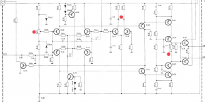
Just a curious note about complexity vs simple design. Here is the original drive circuit for the Tandberg 3012A driving a pair of mosfets per ch. (57V Rails, 2sK175 and2sJ55).
The second pic is obviously The P101 schematic.
I’ve resorted to double dies due to high rail V+/- and Tandberg thought 8A 100V devices could be adequate. The Tandberg power amp. section never failed in the 20+ years I used it. Switches and preamp section were its demise.
Attachments
Final Notes on The P101
Reset the bias to 50 mA. No detectable difference in sound or temp rise to heatsinks at idle. DC balance below 5 mV either channel. Looking at the output on the scope (loaded 8 Ohm and unloaded) it looks good all the way up to 20KHz. No oscillations. I was a little concerned due the fact that the outputs are hard wired off the PCB.
I just upgraded my speakers to the Bryston Mini T's. This amp. drives them cleanly and with authority. Subjectively... no perceptive difference between the P101 and my retired Bryston 3bst. Very satisfied!
Hi
Good that you are satisfied with the sound. I am not surprised that you can not hear difference between 20ma and 50ma bias current because both values are too low...
Normally most lateral mosfet amps have about 130ma bias current per pair (where the temperature coefficient is nullified). For double die, that would be about 260ma. Personally I use even more bias current to have higher power in class A... but for that you need sufficient power heatsinks....
Also 560 ohms gate resistors with double die is an unusual high value.
Fab
Last edited:
Hi
Good that you are satisfied with the sound. I am not surprised that you can not hear difference between 20ma and 50ma bias current because both values are too low...Fab
The last lateral mosfet amp I made had no crossover distortion with zero bias voltage ! In the end I had to set bias current using an ammeter in the power rail.
- Home
- Amplifiers
- Solid State
- Lateral Mosfets Double Die TO-3 ESP P101