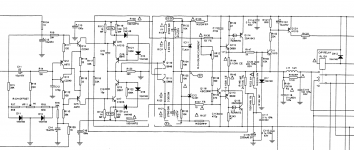
The voltages across the two Zener diodes doesn't sound correct. If you look at the circuit diagram you will see R126 and R127 connect the diodes to the two supply rails.
You should have +46 volts on one end of R126 and -46 on one end of R127. Those resistors should be easy to find as they are larger 2 watt components.
You should have +46 volts on one end of R126 and -46 on one end of R127. Those resistors should be easy to find as they are larger 2 watt components.
That makes the input section very likely the problem.traderbam: I measured R123 and its is 39k (well 38.7k). On powerup it does increase to 1.3V before the cutout click.
If you unplug the link on the back panel for "MAIN IN R-Channel" (I am not looking at the manual so I'm assuming there is some link connecting the pre-amp to the power amp) does the output still drift up to 1.3V? If not, then C11 is the problem.
Otherwise C116 is still a possible cause. The 10 input section transistors (which is a lot) and 4 electrolytic caps are also suspects. I just noticed VR11...hmm.
Also, please confirm that it plays music out of the R channel prior to cutting out.
Last edited:
If those zener readings are right then there is a bigger problem here. Obviously each zener should have 4.7V across it.The voltages across the two Zener diodes doesn't sound correct. If you look at the circuit diagram you will see R126 and R127 connect the diodes to the two supply rails.
You should have +46 volts on one end of R126 and -46 on one end of R127. Those resistors should be easy to find as they are larger 2 watt components.
As Mooly says please check the supply voltages are +46V and -46V wrt ground.
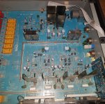
OR the schematic is not the right one for your amp. I'm having trouble finding Q110 in your photo...
Last edited:
So the schematic I posted was for the NAD C320BEE rather than the C320 SM. Some differences. Here's the SM service manual link: NAD C-320 SM Service Manual download, schematics, eeprom, repair info for electronics experts
This one has 39k for R123 and shows some voltages to check.
This one has 39k for R123 and shows some voltages to check.
Attachments
That makes the input section very likely the problem.
If you unplug the link on the back panel for "MAIN IN R-Channel" (I am not looking at the manual so I'm assuming there is some link connecting the pre-amp to the power amp) does the output still drift up to 1.3V? If not, then C11 is the problem.
Otherwise C116 is still a possible cause. The 10 input section transistors (which is a lot) and 4 electrolytic caps are also suspects. I just noticed VR11...hmm.
Also, please confirm that it plays music out of the R channel prior to cutting out.
Yes, It plays sound to both speakers before sound cuts out to both speakers.
At the back there are little metal U shaped connections from pre to main for both L and R. I disconnected them and measured again on speaker. For R it rises to 1.3V as before. For L it just hovers at minus-not-very much. Independent of the presence or otherwise of the PRE-MAIN connectors.
The voltages across the two Zener diodes doesn't sound correct. If you look at the circuit diagram you will see R126 and R127 connect the diodes to the two supply rails.
You should have +46 volts on one end of R126 and -46 on one end of R127. Those resistors should be easy to find as they are larger 2 watt components.
Maybe this was to do with confusion on C320 and C320BEE?
Attached image showing the diodes D11 and D12 that I measured (inside red outlined triangle). On first circuit diagram D11/D12 were listed at 4.7V, but that was for C320BEE. On circuit diagram the C320 I have, D11/D12 are labeled as 1N4148 and look like normal diode symbol, not the symbol for Zener diodes if I understand that correctly.
Attachments
Last edited:
Yes, I think you are right. You'll see four voltages shown on the new schematic, 0.9V across two resistors, +5V and -5V. You should check these.Maybe this was to do with confusion on C320 and C320BEE?
To eliminate C116, try to measure the voltage across R149. It should be near zero at all times. If it increases over time, like the output voltage, then C116 is pants.
The reason R123 voltage is important is that is shows the input stage is not trying to correct the +1.3V error on the output by forcing a large negative voltage across R123. In other words, the input stage thinks it's supplying the right voltage...which it isn't. So either it is being fed an erroneous voltage from the output (such as if C116 is duff) or something in the input stage itself is broken.
We'll find it.
Maybe this was to do with confusion on C320 and C320BEE?
Attached image showing the diodes D11 and D12 that I measured (inside red outlined triangle). On first circuit diagram D11/D12 were listed at 4.7V, but that was for C320BEE. On circuit diagram the C320 I have, D11/D12 are labeled as 1N4148 and look like normal diode symbol, not the symbol for Zener diodes if I understand that correctly.
The new circuit shows IC11 and IC12 which are programmable voltage references and these are used in place of ordinary zeners.
The important thing is that you have the plus 5 and minus 5 volts as marked on the diagram.
Something else to check. I see the input transistors are biased solely through the wiper of a preset (VR11 offset). You could try measuring the voltage at the junction of C11, R14 and R15 and seeing if it is stable or whether it varies/drifts as the fault appears.
update
My apologies for long delay in adding to this, I had some personal issues and was away from home.
I made several measurements:
R123 and R223 both have resistance around 39kOhm, R123 slightly less (38.7) and the other bang on 39. On power when I measure V on R123 and it increases to 1.3V quickly (over about 50 seconds), then very slowly to around 1.31V and the safety circuit cuts in (another 20 seconds). R223 as comparison does not increase at all.
For R126 I measured resistance and on my meter is slowly rises to about 1.17 kOhm. For R127 the same except it goes a bit higher, to 1.3 kOhm. If I understood color coding correctly these are 1.5kOhm resistors? When I apply power and measure V I see R126 is 38V and R127 is 41V. Neither is that close to 46V. I measured several times and results were consistent.
On R149 when I measured it just stays around 0V all the time, so does that mean C116 is not pants?!
As for "You could try measuring the voltage at the junction of C11, R14 and R15" I am not sure the ask? How to do that? Where do I put my probes? I did measure the resistance for R14, 100Ohm and R15, 21,5kOhm. Same as R24 and R25 in fact.
Last edited:
No problem ")
The voltage measurement is where those three parts meet, so if you look at the circuit that could be the plus end of C11 or (because its so low in value) either end of the 100 ohm (R14).
Black lead to chassis, red lead to do the measurement. Use a low voltage DC range on the meter.
The voltage measurement is where those three parts meet, so if you look at the circuit that could be the plus end of C11 or (because its so low in value) either end of the 100 ohm (R14).
Black lead to chassis, red lead to do the measurement. Use a low voltage DC range on the meter.
No problem
The voltage measurement is where those three parts meet, so if you look at the circuit that could be the plus end of C11 or (because its so low in value) either end of the 100 ohm (R14).
Black lead to chassis, red lead to do the measurement. Use a low voltage DC range on the meter.
Thanks Mooly!
I measured at all 3 points and voltage is very low when power is on, +3.3 mV or so, and stays basically constant until and after the safety cuts in.
After I shut power off the meter then jumps to -170 mV or so which then goes down slowly, presume some capacitor is discharging?
That sounds normal but it had to be checked.
You are going to have to work on this in the faulty state and make very careful voltage measurements. The clue will be in interpreting those readings and seeing where the 'loop' fails. With the input at the measured 3 millivolts or so you will see the feedback voltage rise on R115/116 junction.
The problem could be a slightly leaky semiconductor (transistor or diode) but it probably wont be very obvious. Freezer spray used very very sparingly on suspect devices might help locating the issue.
A check with an oscilloscope is also always a good idea. Although unlikely, there could be some very high frequency instability shifting the DC operating point.
Hi
The electrolytic s in them amplifiers are really not to be trusted. I have owned a few of these in the past and found the capacitors to dry out with no evidence of leaking electrolyte. In the main psu caps the internals could be heard rattling around inside . I would suggest you change all electrolytics to start with .
Ian
That sounds normal but it had to be checked.
You are going to have to work on this in the faulty state and make very careful voltage measurements. The clue will be in interpreting those readings and seeing where the 'loop' fails. With the input at the measured 3 millivolts or so you will see the feedback voltage rise on R115/116 junction.
The problem could be a slightly leaky semiconductor (transistor or diode) but it probably wont be very obvious. Freezer spray used very very sparingly on suspect devices might help locating the issue.
A check with an oscilloscope is also always a good idea. Although unlikely, there could be some very high frequency instability shifting the DC operating point.
Sorry, I have no oscilloscope available (and would not have clue to use it).
The measurement at that junction is shown as 3.3 / 3.4mV, both before the "fail" and after. It barely deviates. This is lowest setting I have for DC on my multimeter so I cannot be more precise.
I am a little lost now. I don't really understand the line of thought here as to what might be wrong, and which test result either confirms or eliminates the theory? Is 3mV indication of an issue?
Earlier I was asked to check R126/R127 for 46V and found neither was very close to 46V, also not that close to each other in fact. Is that not an indicator of an issue?
Hi
The electrolytic s in them amplifiers are really not to be trusted. I have owned a few of these in the past and found the capacitors to dry out with no evidence of leaking electrolyte. In the main psu caps the internals could be heard rattling around inside . I would suggest you change all electrolytics to start with .
Ian
Thanks for replying.
Does the various measurements made / evidence collected indication of an issue with main PSU caps? I am loath to start changing things, with all the risks of an amateur like me making things worse, without evidence to indicate there is specific fault? How to confirm a fault there?
I am also loath to reject ideas from someone who knows more about these things than I do, and has "experience" which is much under-rated diagnostic tool! But replacing "all electrolytic" is not something I would easily undertake on my own.
The 3.3mv is normal and very very close to the theoretical zero volts. Any voltage at the this point (the input to the amplifier) would be amplified just like the wanted audio signal.
So we had to make sure that the input of the amplifier was at 'zero' when the fault appeared. And it is.
The whole amplifier relies on the action of negative feedback to stabilise the operating point of the output and ensure it is close to zero volts.
There are actually two inputs to the amplifier, the one we have measured at 3.3 mv and this is called the non inverting input. The second input is called the 'inverting input' and is where the feedback is applied. This point is the junction of R15 and R116.
Just like an integrated circuit 'opamp', the amplifier output should assume a voltage that will keep the difference in voltage between these two inputs at zero and that does not seem to be happening when your fault appears.
This R126/127 voltage is actually a measure of the supply voltage... do we know what that is ? The voltages you mentioned of 38 and 41 sound reasonable enough. R126 should be PLUS say 40v and R127 NEGATIVE 40 volts.
What voltage do you measure on the other end of those resistors ?
You could buy a capacitor esr tester i am sure a decent one will cost much more than the price of having fresh capacitors installed in your amplifier .. the capacitors may be ok, but from experience some of them will surely be way off spec. you may be successful in repairing the amplifier but you will inevitably need to replace at least some of the electrolytic's . This is a guarantee
This R126/127 voltage is actually a measure of the supply voltage... do we know what that is ? The voltages you mentioned of 38 and 41 sound reasonable enough. R126 should be PLUS say 40v and R127 NEGATIVE 40 volts.
What voltage do you measure on the other end of those resistors ?
So, to be clear, the first measurements for these 2 were with multimeter probes connected to both ends of the resistor, I cant recall which way round. I wrote:
"For R126 I measured resistance and on my meter is slowly rises to about 1.17 kOhm. For R127 the same except it goes a bit higher, to 1.3 kOhm. If I understood color coding correctly these are 1.5kOhm resistors? When I apply power and measure V I see R126 is 38V and R127 is 41V. Neither is that close to 46V. I measured several times and results were consistent."
Using "Black lead to chassis, red lead to do the measurement" I made now 4 new measurements, both ends of each resistor and watched result from power on until the fault "click" is heard.
R127 (one end) : MINUS 3.75 --> MINUS 3.66
R127 (other end) : MINUS 44.7 --> MINUS 45.0
R126 (one end) : PLUS 6.21 --> PLUS 6.36
R126 (other end) : PLUS 44.4 --> PLUS 44.9
That there is quite an asymmetry here strikes me as perhaps helpful/informative.
traderbam posted that NAD C-320 SM Service Manual download, schematics, eeprom, repair info for electronics experts is link to correct C320 manual (i.e. not the C320BEE that confused us earlier).
There does seem to be a problem with those voltages. The -/+ 45 (approx.) is fine and is the unregulated rails.
The voltage on the other end I think should very close to 5 volts (and that is in fact marked as such). The voltage can be calculated from the formula applicable to the TL431 programmable Zener and is (R132/R134) + 1 and then multiply that by the internal fixed reference voltage of the TL431 which is 2.5 volts. So I agree the 5 volts shown in the manual.
The question is why are the voltage wrong. A low voltage could be because something draws to much current and pulls it down. A high voltage could be failure of the TL431 or something 'pushing' to much voltage into such that it can not regulate.
Lets concentrate on both of these incorrect voltages, and there are a few possibilities for you to check.
1/ You need to measure the value of R127 and R129 out of circuit. You can do this by just unsoldering one end of each and then measuring.
2/ Do the same for R126 and R128. If they are all OK then resolder them back.
3/ Check in circuit R124 and R125 (these are low value resistors and should be accurately readable). If you find you can not read them in circuit then unsolder one end and check.
4/ There is no easy way to test the TL431's. The only definitive method would be for you to replace them, however they are probably not the most likely suspect. You could swap them both with the other channel as a test.
5/ I suspect there is a fair chance the problem could be with one of the transistors Q18 and Q19 or Q112 and Q113. measuring base/emitter voltages on these when the fault occurs would be worthwhile. You are measuring across the base emitter junction and looking for deviations from the expected 650mv (approx.) Typically the voltage would be significantly higher indicating a problem with that transistor.
- Status
- This old topic is closed. If you want to reopen this topic, contact a moderator using the "Report Post" button.
- Home
- Amplifiers
- Solid State
- NAD C320 woes