1/ You need to measure the value of R127 and R129 out of circuit. You can do this by just unsoldering one end of each and then measuring.
You mean measure resistance, right? Curious, why must it be out-of-circuit?
5/ I suspect there is a fair chance the problem could be with one of the transistors Q18 and Q19 or Q112 and Q113. measuring base/emitter voltages on these when the fault occurs would be worthwhile. You are measuring across the base emitter junction and looking for deviations from the expected 650mv (approx.) Typically the voltage would be significantly higher indicating a problem with that transistor.
Er, can you confirm where do I put red/black probes and which setting on the multimeter (guessing low range DC mV).
thanks again, RT
You mean measure resistance, right? Curious, why must it be out-of-circuit?
If you leave a resistor in circuit when you measure it, you cannot be certain that the multimeter is giving you an accurate result.
For example, if there are multiple resistors in parallel within the circuit, the total resistance measured would be 1/RTot=1/R1 + 1/R2 + 1/R3 +...+1/RN.
A simple example of this is 3x 1k resistors in parallel would look like 333.3 ohm to the DMM.
By desoldering one leg of the resistor under test, you are breaking any influence of the circuit on that particular resistor.
Er, can you confirm where do I put red/black probes and which setting on the multimeter (guessing low range DC mV).
DC mV as you are looking for a 0.6v (650mV) drop across the transistor Base/Emitter junction for the transistor to be conducting.
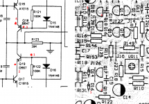
See the attached schematic sample and (should be) the corresponding points on the PCB for Q18 and Q19 to get you started.
For Q18 Base, use D15 Cathode (striped end) and for Q19 Base, use D16 Anode (opposite end to stripe).
Shouldn't really matter which orientation for the red/black probes (yeah, I know, not best practice), you are just looking for the 0.6v at this stage.
Attachments
You mean measure resistance, right? Curious, why must it be out-of-circuit?
Er, can you confirm where do I put red/black probes and which setting on the multimeter (guessing low range DC mV).
thanks again, RT
Pretty much as avtech mentions above. Any parallel resistance will influence your result plus any slight residual voltage (from the PSU caps) can totally confuse the reading from a DVM. Also, depending on the test voltage that the meter uses you can find that various semiconductor junctions become active and again sway the result.
The base/emitter voltage seen across a normally operating transistor is determined by the physics of the materials used and that means for normal silicon devices it will be in the 600 to 800 millivolt region.
An NPN device (those with the arrow on the emitter pointing outward) will always have the base as the highest of the two, the PNP's (arrow pointing in) will have the emitter as the highest.
So to measure this you place the leads on the device itself. Be extremely careful not to short any pins as that could result in instant catastrophic failure of several components.
Hi
To let the people who helped me on this know how the story ended ....
The thread got a bit too technical for me, so I took to a local (in Germany) repair guy from a large retail chain (Euronics for those that might know them, kind of German version of Curry's). He said he'd look at it for 20 euros, and let me know how much repair would cost after examination.
About 3 weeks later he told me he'd changed (sic) some components, though he hadn't documented which ones, but had not succeeded to fix or find the fault. He was prepared to look more, but estimated 200 euros for his time to repair, and basically gave me no confidence he knew what he was doing. In meantime I'd found a specialist hifi repair guy in Glasgow who sounded more experienced, and I was going to go Glasgow anyways, so I collected it and took it with me (some strange looks going through security at airport!)
It happened Glasgow guy had another NAD amp on his workbench the day I delivered mine, so I felt quite optimistic. I told him 100% truth about fault, history, german guys attempted repair, asking on this forums, etc.
But Glasgow guy took a look, and wrote:
-->
Repair not being carried out on unit ref. following. Various Transistors / Capacitors have been replaced with PCB Print / Etching having been linked up via wire connections across print during previous repair / inspection. Not to a satisfactory standard in my opinion. may be untold further fault/s within unit. Outwith previous work having been carried out, Main Smoothing Capacitors require replacing along with various Electrolytic Capacitors and Resistors in Power Regulator Circuit and Audio Output Circuit. Aforementioned should have been attended to during previous inspection.
-->
I've basically given up as amp is now in Glasgow, I am in Germany, and no real hope for a repair.
I think 3 lessons learned for me are:
a) it was error to let German guy have a look
b) telling the whole truth to Glasgow guy was mistake
c) I should have time-boxed things from the start - a few hours in I should have realised it was not going to be simple and therefore beyond my capacity/ability.
I'm now torn between buying a second hand C320/C320BEE, or a new amp entirely (I demo-ed a Onkyo A-9010-S and it sounded good to me!)
Thanks for updating the thread, and I'm sorry the amp seemed to get 'butchered' by the Euronics guy (we have or have had the Euronics chain here in the past).
All you can do is chalk it up to experience and definitely don't let it put you off looking at stuff in the future.
Good luck with the new amp hunting")
All you can do is chalk it up to experience and definitely don't let it put you off looking at stuff in the future.
Good luck with the new amp hunting
- Status
- This old topic is closed. If you want to reopen this topic, contact a moderator using the "Report Post" button.