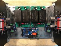
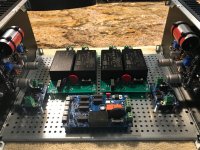
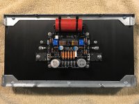
Well, if my play on words in the title did not give it away, the first two photos certainly will. Yes, no big toroids or caps, but two +/-24V switch mode power supplies. They are the SMPS-86 power supplies designed by Tom Christiansen of Neurochrome SMPS-86. Each supply will produce 2.5A with a max ripple voltage of 2.85mV RMS. These are the same supplies (+/-12V version) which I used in my MoFo monoblock amplifier build; a very nice sounding little Class A amp Build This MoFo!. For this build, I believe the SMPS supplies will be a good candidate based on the push-pull design and relatively high PSRR of the USSA-5 circuit. If the sound quality is sub-par to what is expected (I do not anticipate this happening), I have a pair of Prasi CRC boards which will drop into the same footprint as the SMPS-86.
The chassis is a Dissapante 4U, 300mm deep with a perforated steel mounting plate offered thru the diyAudio store. The two small boards left and right of the power supplies are Tom's new Guardian-86 speaker protection boards Guardian-86: Speaker protection board for LM3886-based amplifiers (and others)., and the larger board behind the supplies is his new ISS: Intelligent Soft Start ISS: Intelligent Soft Start. If this all seems like an advertisement for Neurochrome, it is not. For me, Tom's designs have proven to be of sound engineering design and quality.
The USSA-5 boards were constructed using all of the standard BOM parts with the exception of the input capacitor and thermistor. The large input capacitor is a Jantzen Audio Superior Z-Cap (4.7 uF, 800V) and is mounted to the heatsink using two cable tie anchors. The thermistor is from Digi-Key (P/N BC3399-ND) and mounts to the heatsink using a #6-32 screw and washer. I elected to use Keratherm pads under each of the FETS, available from diyAudio store.
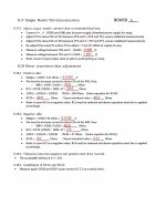
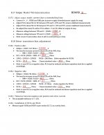
To date, the boards are tested and complete up to section 8.18.4 Installation of RV1A and RV2A. The following are the results of my Output MOSFET VGS determination. More details to follow after Mouser delivers and wiring begins.
The chassis is a Dissapante 4U, 300mm deep with a perforated steel mounting plate offered thru the diyAudio store. The two small boards left and right of the power supplies are Tom's new Guardian-86 speaker protection boards Guardian-86: Speaker protection board for LM3886-based amplifiers (and others)., and the larger board behind the supplies is his new ISS: Intelligent Soft Start ISS: Intelligent Soft Start. If this all seems like an advertisement for Neurochrome, it is not. For me, Tom's designs have proven to be of sound engineering design and quality.
The USSA-5 boards were constructed using all of the standard BOM parts with the exception of the input capacitor and thermistor. The large input capacitor is a Jantzen Audio Superior Z-Cap (4.7 uF, 800V) and is mounted to the heatsink using two cable tie anchors. The thermistor is from Digi-Key (P/N BC3399-ND) and mounts to the heatsink using a #6-32 screw and washer. I elected to use Keratherm pads under each of the FETS, available from diyAudio store.
To date, the boards are tested and complete up to section 8.18.4 Installation of RV1A and RV2A. The following are the results of my Output MOSFET VGS determination. More details to follow after Mouser delivers and wiring begins.
Attachments
Last edited:
Nice build ")
I used SMPS in my class A ALPHA , I did not have good luck with regular SMPS from amazon or ebay so I used 4x180W HP laptop power supply (built to last and low noise), followed by boost board to bring it to 24v and Juma's CapMX and very generous CRCRC filter, there's no audible noise and the power supplies don't break a sweat.
Good luck on yours
- Status
- This old topic is closed. If you want to reopen this topic, contact a moderator using the "Report Post" button.
- Home
- Amplifiers
- Solid State
- My USSA-5 Build ... Switched at Birth