The surprise for me was that MATE turned out to run much faster than both LXDE and XFCE (both frequently touted as "light" desktop environments.)MATE is one of the best lightweight Linux desktop environments
I have no previous experience with MATE, though I have been Linux-only in my personal life for most of two decades now. By the time MATE came along, I had switched to XFCE to avoid the growing disasters that both Gnome and KDE had become.
There is a build of Tiny Core Linux for the RPi, and that holds promise to be much lighter than even MATE. Tiny Core does require some tinkering, though, while Ubuntu MATE worked flawlessly for me right away.
That's pretty much the plan. I have the beefy music stand already. The devil is in the details - protecting the Pi from physical damage, figuring out what to do with the jumble of cables and power supplies, and either packaging a mouse and full-size keyboard with the RPi (which means building a keyboard tray on the music stand), or finding some other more compact user interface.Can you not mount the Pi & sound card on the rear or the monitor first, then attach that to a music stand? It would need to be a fairly sturdy stand to take the weight!
I bought one RPi case that turned out to be both crude and poorly designed - I need tweezers to insert or remove the micro SD card.

-Gnobuddy
Gnome 3 and Unity are particularly 'special' DEs! Why these were traded for Gnome 2's highly productive interface, I cannot imagine. Maybe it's an age thingI have no previous experience with MATE, though I have been Linux-only in my personal life for most of two decades now. By the time MATE came along, I had switched to XFCE to avoid the growing disasters that both Gnome and KDE had become.
I'll look into this, although I normally use RPis as GUI-free headless devices, such as VPN servers, Wi-Fi hotspots and firewall/routers.There is a build of Tiny Core Linux for the RPi, and that holds promise to be much lighter than even MATE. Tiny Core does require some tinkering, though, while Ubuntu MATE worked flawlessly for me right away.
Good luck with your RPi ruggedisation!
Mebbe both age, and Apple-thinking. In a few more years, I expect the standard computer/phone user interface will be a single large happy smiley-face icon that fills the screen; you poke at it with your thumb, it takes a selfie of you, uploads it all over the Internet, winks at you, phones home to Apple's server-farm and uploads your DNA sequence, plays you a short video of a kitten falling off a flower-pot, and finally uses AI to try to guess what you actually wanted to do.Maybe it's an age thing
The iSmile will be the only way you can interact with your Apple device.
Linux will have a similar interface, the oh-so-cleverly named xiSmile (the x is silent.)
Android will have a friendly cat face instead, known as CougarLollipop.
And Microsoft? They'll bring back Clippy.

If it's an Apple device, it will also come with only the shiny new Dunderbolt interface, which replaces all previous interfaces including the Apple Display Connector (APB), USB, HDMI, Lightning, etc.
Unfortunately, the new Dunderbolt interface only works with Dunderbolt-compatible accessories sold or approved by Apple. A Dunderbolt-compatible set of ear-buds is available for a mere $499.99 USD.
I'm off to file a patent for the iSmile concept. If Apple's legal department hasn't already done so, that is.
-Gnobuddy
There are rumours there will be yet another new Apple product, complete with direct neural interfacing (DNI). The user interface is expected to be USB-based using the latest USB-F connector with a bandwidth rating of 40GB/s. This permits insertion that’s not only fully reversible, but also infinitely reversible and is fully backwards compatible with a 3.5mm jack plug. A USB-F socket is conveniently installed at the back of the user’s head, thus avoiding physical connector damage should the user become distracted and inadvertently walk into a virtual blue-screen wall (originally developed by Microsoft). It is envisaged that this will be known as the iScream. To avoid ground loops, a fully synthesised diode-and-resistor-free ground lift system is in development based on ‘70s footwear technology, codenamed “Platform-lift”. This easily achieves the required minimum 3” (76.2mm) separation from reality.Mebbe both age, and Apple-thinking...
Research has shown great enthusiasm for this product as every member of the trial team was found to utter a variant of the product name on insertion of the neural connector.
Android have expressed an interest in forming a merger with Apple using their latest V45.0 Sandwich OS and anticipate the joint venture could be named iScream-Sandwich. Sounds familiar?
Last edited:
This simple amplifier is a temptation...
Hi all, back on topic, please.
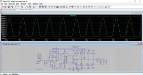
Although, I have designed several variants of the same amplifier with good distortion figures, this particular circuit seems to offer what other similar circuits did not offer: it has a distortion below 0.06% and a very low DC offset voltage at the output. This uses a high voltage cascoded input stage to allow the use of low voltage input transistors and provide high voltage isolation from the input. A cascode also provides other advantages from an electronics point of view with a higher input inpedance and a drastic reduction of the Miller effect since Vce is esssentially constant on the input transistors.
Hi all, back on topic, please.
Although, I have designed several variants of the same amplifier with good distortion figures, this particular circuit seems to offer what other similar circuits did not offer: it has a distortion below 0.06% and a very low DC offset voltage at the output. This uses a high voltage cascoded input stage to allow the use of low voltage input transistors and provide high voltage isolation from the input. A cascode also provides other advantages from an electronics point of view with a higher input inpedance and a drastic reduction of the Miller effect since Vce is esssentially constant on the input transistors.
Attachments
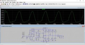
The output waveform looks good but a deeper investigation shows underlying problems that must first be addressed. Ib(Q13), LTSpice notation, has a strong ringing component at both ends of crossover. Zooming on the ringing shows typical damped sine oscillations at a supersonic frequency. Physics state that is is simple harmonic motion which requires a specific mechanism to occur. In mechanics such a mechanism, is a force that is proportional to displacement from a fixed point but always pointing to that fixed point. In electronics, one must have two mechanisms that mutually exchange energy. A series LCR circuit is such a circuit. But where is such a ghost circuit in the VAS stage of this amplifier? Yes, there is Cbc, the base-collector NON-LINEAR capacitance, that can store energy, but what is the invisible 'spirit' that mutually exchanges energy with Cbc?
Unless, I understand the underlying mechanism, I am afraid, groping in pitch dark with LTSpice is of very little use. I am tempted to attribute this ghost mechanism to other less known parasitics which may behave like an inductance. I am also assuming LTSpice has no knowledge to calculate parasitic inductances as these depend on the circuit assembly.
Post Scriptum:
I found that increasing the VAS's standing current, quiescent current?', greatly attenuates the ringing, but a VAS with several tens of milliamperes is more unnecessary stress on the VAS's transistors.
OK then...
so I tried this on Doug Selfs blameless class B and that to behaves the same as yours. I'm wondering if this is an effect that can be partly blamed on the models used. Substituting your drivers for MJE243 and MJE253 and also changing the outputs to MJL21194 and MJL21193 seems to resolve the issue. Bias at 30ma per pair.
so I tried this on Doug Selfs blameless class B and that to behaves the same as yours. I'm wondering if this is an effect that can be partly blamed on the models used. Substituting your drivers for MJE243 and MJE253 and also changing the outputs to MJL21194 and MJL21193 seems to resolve the issue. Bias at 30ma per pair.
Attachments
It seems I need to boost my understanding more with more reading. This journey is a learning adventure of someone who is well past his schooling years. Douglas Self says that these ghost oscillations are not yet fully understood and that they are the result of the VAS stage being seen as inductive by the driver stage.
The solution seems to be using a higher, 47mA, bias current for the output. This, unfortunately, is per output transistor, which means, a total of 160mA will be wasted continuously. I think, I have to be contented with reality, as this power stage is a large one, and one cannot feed giants on bread crumbs! If I remember correctly, Class AB use higher bias currents to force both NPN and PNP transistor to turn off a short while after crossover is reached. This unattractive energy waste should give better performance benefits: we will see.
I will do more testing. If this simple circuit passes all tests, it will be built, I already have a PCB layout drawn. Its simplicity means the tempting manual method can be used to get it ready in a few hours.
I will do more testing. If this simple circuit passes all tests, it will be built, I already have a PCB layout drawn. Its simplicity means the tempting manual method can be used to get it ready in a few hours.
Attachments
Last edited:
I think you do have to try it for real at some point and see how reality matches up to the simulation. If you remove the 1uF output load, reduce the input voltage to say 0.1 volts and reduce the bias to zero then there are oscillation issues on the output. Increase the bias to just a milliamp or two and they vanish. There might not be much you can do about that and it could well be a non problem anyway.
Attachments
Before dirtying my hands by actually building this amplifier, I am referring to last the one, I will try to compare it with other amplifiers that are posted here. The uploaded circuit should be in .asc format so that I would be able to readily simulate it. I need to know how much ringing is tolerated in the drivers of other amplifiers that are known to perform well and to have a good reliability.
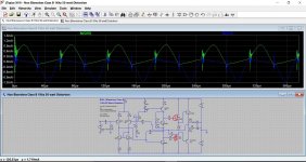
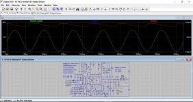
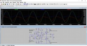
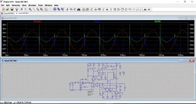
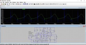
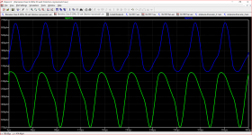
Try these. It's surprising just how distorted and 'ringy' driver currents can be.
Attachments
-
Blameless Class B 20Khz 50 watt Distortion.asc7.4 KB · Views: 93
-
 Capture4.JPG274.3 KB · Views: 79
 -
 Capture3.JPG300.5 KB · Views: 75
 -
 Capture2.JPG252.8 KB · Views: 186
 -
 Capture.JPG265.1 KB · Views: 225
 -
Elektor 741 Current Dumping Amplifier.asc5 KB · Views: 39
-
Quad 303.asc7.9 KB · Views: 38
-
FV V6_0 Vertical FET Folded Drivers.asc19.3 KB · Views: 37
Thanks for those circuits. All of them have considerably less ringing than my circuit which means I am still not ready for the real thing. I am posting my latest update of the amplifier circuit which seems to have an improved distortion figure and considerably less ringing than the previous circuit. At 16kHz, the distortion: 0.023648%(0.023715%) At 1kHz, the distortion: 0.021927%(0.029916%) [There is absolutely no ringing at Ib(Q13)]
Attachments
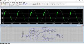
I looked at the Blameless attachment you included with post 177 and ran the simulation. Somehow the type of transistor used for Q9 is absent.
I associate ringing as having to do with reactance which will be present in a speaker load.
With that worry in mind I made some alterations to your simulation to see if it might be possible to resolve that issue.
The evidence in the attachment shows the shapes are still distorted but there is no ringing. An improvement in THD to 0.007% (0.01 % normalised) was noted. This is getting a little off topic but I can post my .asc file if there is any interest.
As far as the project amplifier is concerned I would hesitate to build something as big as this without running a Tian test for stability on the final version of the circuit.
Attachments
- Home
- Amplifiers
- Solid State
- My attempts at a design of a 3 stage amplifier