") A big difference overall.
A big difference overall.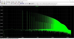
I am trying to avoid having to use additional 100V, 1000uF capacitors to keep down the costs and to avoid mounting problems. The space inside the amplifier box is getting limited, therefore, I am seeking other ways of decoupling the power supply. Using a diode-resistor-capacitor arrangement seems to work with a much smaller capacitor. However, the ripple at the output has increased by 250%. Using a slow speed mains frequency rectifier diode, has the additional side effect of being unable to pass high frequency interference signals. This side effect complements the filtering ability of this simple filter.
With four axial 100V, 100uF electrolytic capacitors, four ordinary rectifier diodes and four 100 Ohm resistors, these filters should be possible to implement without additional mounting and space problems.
I have omitted the 100nF capacitors. If their function is necessary, please post. I am attaching the resultant circuit.
The purpose of those 100nF capacitors must be to shunt any RF signal incoming from the mains and rectifier brige. Having a rectifier bridge presents a stream of wave trains at 100Hz which explains why my ear picked that frequency. Since the amplifier was never tested on load, the power supply ripple itself should not be the cause, as without an amplifier load, it should be negligible.
This reasoning is telling me, I can filter this interference with yet smaller electrolytics, but with the latest arrangement, and the 100nF capacitors.
Attachments
Decoupling can also be to prevent turning the amplifier into a high frequency oscillator. The power rails can act as feedback paths if not adequately decoupled. For peace of mind don't remove rail decoupling in a power amplifier without thorough stability testing, oscillation at full power will do a lot of damage.
I removed the DC voltage sources and replaced them with a rectifier bridge, and two AC voltage sources to mimic the action of the toroid's secondary. LTSpice is NOT capturing any RF interference signals at the rectifier diodes, and the current curves are very smooth, implying good simulation resolution. The output is also very clear of interference. This is making me conclude it is the mains supply that is the real source of this interference. Where I live, many people do not careless about not polluting the mains supply: that is totally alien to them. As long as their appliances do not break down, and as long as their electric motors work, it is all right for them. This means, I need to create an interference source with frequent, but random bursts of frequencies as seen on the oscilloscope.
As you can see, I am very reluctant to start modifying the amplifier before studying in depth the cause of this issue. Simulations show that the actual ripple with no load is 200mv peak to peak, which should not cause series issues like this. Also, the fact that at some times, there was no hum, corroborates my conclusion that it is the mains supply that is causing all this. At present, around my home there is a building frenzy with electric crains that use relays that can be heard clicking from over 100m.

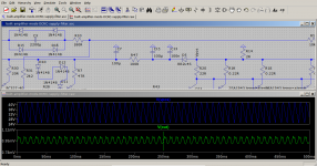
Modifying further the DRC filter to use two 100uF capacitors one directly after the diode and another one after the resistor, resulted in a ripple reduction of 17/0.2 = 85 times. The amplifier's power supply was simulated with a 2 Ohm resistor connected from rail to ground on both rails to simulate extreme loading. I am posting a screenshot of LTSpice with the output and Fourier Transform.

Post Scriptum:
Adding a 100p capacitor immediately before the rectifier and two 1uH inductors at the secondary windings' output resulted in heavy 2000Hz charging current oscillations with an amplitude of 60A. The output still seems immune to this according to LTSpice.
I will further increase the frequency to see what happens to the output.
I ordered those four chunky, 100V, 1000uF electrolytics, another four 0.1uF Mylar capacitors and a packet of 10 22.1 Ohm resistors. In the meantime, I will make the PCBs and plan where they will be securely installed. I will build the filters as suggested by Mjona.
As you can see, I am very reluctant to start modifying the amplifier before studying in depth the cause of this issue. Simulations show that the actual ripple with no load is 200mv peak to peak, which should not cause series issues like this. Also, the fact that at some times, there was no hum, corroborates my conclusion that it is the mains supply that is causing all this. At present, around my home there is a building frenzy with electric crains that use relays that can be heard clicking from over 100m.
Modifying further the DRC filter to use two 100uF capacitors one directly after the diode and another one after the resistor, resulted in a ripple reduction of 17/0.2 = 85 times. The amplifier's power supply was simulated with a 2 Ohm resistor connected from rail to ground on both rails to simulate extreme loading. I am posting a screenshot of LTSpice with the output and Fourier Transform.
Post Scriptum:
Adding a 100p capacitor immediately before the rectifier and two 1uH inductors at the secondary windings' output resulted in heavy 2000Hz charging current oscillations with an amplitude of 60A. The output still seems immune to this according to LTSpice.
I will further increase the frequency to see what happens to the output.
I ordered those four chunky, 100V, 1000uF electrolytics, another four 0.1uF Mylar capacitors and a packet of 10 22.1 Ohm resistors. In the meantime, I will make the PCBs and plan where they will be securely installed. I will build the filters as suggested by Mjona.
It is hard to read some of the images for your power supply however if you are up for redesigning your boards you might consider a separately rectified supply for the small signal stages.
These are not going to demand much current from the transformer so the ripple will be less from this reason plus the isolation from the main rectification for the output stage.
The charging currents for capacitors occur on half cycles towards the peak of a 50 cycle mains frequency so the larger the peak current drawn is the larger the ripple spike will be since the charging has to happen in the same length of time.
You will have to test this by simulation however the best outcome might be achieved by reducing the capacitors supplying the output stage to 2000uF and making those for the small signal stages double at 4700uF.
There is an example of a Rotel high power amplifier in Linsley-Hood's book about Valve and Transistor amplifiers. I am away from home at present and will be until Monday week and I don't have the exact details but if you are interested I can give these later.
My thinking is if space is a problem this scheme may give the results you want within less space.
Also you could put the RC network on a board with the separate rectifiers ( 1A types will do) for the small signal supply in which case you could use your existing power amplifier boards by using a spot face cutter tool to separate the feed to the small signal stage - neatly and drill holes for a pcb pin or header to take the connection from the separate supply.
Last edited:
To avoid having the filters' 1000uF capacitors from feeding current to the output stage when the voltage of the main reservoir capacitors drops, I inserted a rectifier diode on both rails. The result is a reduction of 50% of the ripple at the output. Therefore, I will add a diode to the each filter. Simulations are showing that this is equivalent to using a separate power supply. In fact, the inrush charging currents drop to zero every half cycle like what happens with a separate transformer winding and rectifier.
The next 'problem' to solve is to sufficiently block incoming RF interference like that encountered with unclean mains. I am referring to interference that is emitted by large currents being cut off, interference from triacs and thyristors, unfiltered drills, insufficiently filtered switch-mode-power-supplies, malfunctioning power inverters, etc. I am not planning to use my amplifier near a radio repeater churning RF power at several megawatts.
P.S. (an anecdote)
I remember once I was told a large crane was being used near a 1 MW, 1.6MHz radio repeater. The size was such that resonance was set up and the crane started to get hot. To continue working, the repeater had to be temporarily switched off.
P.S. (an anecdote)
I remember once I was told a large crane was being used near a 1 MW, 1.6MHz radio repeater. The size was such that resonance was set up and the crane started to get hot. To continue working, the repeater had to be temporarily switched off.
Wow, that sounds scary and yet you can absolutely imagine something like that happening under the right conditions.
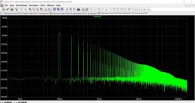
With the filters in the circuit attached to this post, I am getting these results:
One such filter is shown. It is made up of C7, C15, C13, R47 and D5
Rail ripple (intentionally made huge): 41.8V - 25.2V = 16.6V
RF voltage superposed on -ve rail: 50mV @ 200kHz
Results (after filters):
Minor rail voltage ripple (for sensitive parts): 1.02mV - 0.91mV = 0.21mV
RF voltage: 1.09mV - 0.81mV = 0.28mV
RF attenuation factor: 50mV/0.28mV = 178.6
Ripple attenuation factor: 16.6V/0.21mV = 79.0
RF attenuation in dB: 20*log(178.6) = 45dB
Ripple attenuation in dB: 20*log(79.0) = 38dB
Post Scriptum:
The space issue and my intention of using the existing PCBs favour using this filter as it uses far less bulky components. It is also more effective to reduce ripple but less effective on reducing RF.
I have a blank PCB sheet, electrolytic capacitors, polyester capacitors, resistors and diodes. This should enable me to build the filters PCBs. Hopefully, the amplifier output will be quieter with no audible hum and other noises.
Attachments
The point I am about to make has probably been made before - this is to add capacitors in parallel with the diodes in the bridge rectifier. The separate rectifier scheme for the small signal section is better since the large half wave signals induced by the output stage at high powers will provide the best isolation. These will still get through the extra diode you have added in the line to the small signal section - albeit mitigated by the RC filter.
If you run with this dual supply system add the suggested capacitors in parallel with the diodes in the power section bridge rectifier.
If you run with this dual supply system add the suggested capacitors in parallel with the diodes in the power section bridge rectifier.
Thank you for posting. The existent rectifier bridges are accessible with a rating of 400V, 25A. If I were to solder a filtering capacitor across the four diodes, which capacitors would you suggest? The rectifier bridges already have a filtering capacitor across the AC terminals.
With the power level of your amplifier it would be useful to replace the potted bridge with one having a higher current rating.
The conventional filter arrangement is to fit a capacitor between each secondary and the transformer center tap which connects to earth.
The idea of a parallel capacitor in parallel with a rectifier diode is not too far removed from that of the capacitor across the points in the long outmoded Kettering ignition system.
The spark plug leads in these systems also serve to suppress e.m.i. which interferes with television reception. A neighbour in the vicinity of the property where I am holidaying at has a lawn mower which does that.
Does anyone know what capacitance is used and what voltage?mjona said:The conventional filter arrangement is to fit a capacitor between each secondary and the transformer center tap which connects to earth.
Inspecting the power supply it has two identical centre tapped secondaries. The filter capacitors on these coils are not identical in value although the secondaries are designed to deliver the same power.
Are the linked capacitors suitable for such a filter?
0.1uF 630V Mylar Capacitor
Both secondaries supply the same power at the same voltage. Each coil powers a separate amplifier channel. That is why it is weired to have two different valued capacitors across the secondaries.
0.1uF 630V Mylar Capacitor
Both secondaries supply the same power at the same voltage. Each coil powers a separate amplifier channel. That is why it is weired to have two different valued capacitors across the secondaries.
I suggest using X2 rated metallised polypropylene 275/250 VAC for both sets of secondaries. The different capacitor values could be due to the properties and design of the mains transformer. Perhaps one set of the secondaries is overlaid on top of the other.
Having intimate proximity, there could be some interaction if the current demands are heavy on both sets, and simultaneous. If space is a problem inside your chassis the transformer rating might have been a compromise and a lower value capacitors on one secondary helps to avoid saturation of the core. I would not increase any of the supply capacitor values over the original figures.
Having intimate proximity, there could be some interaction if the current demands are heavy on both sets, and simultaneous. If space is a problem inside your chassis the transformer rating might have been a compromise and a lower value capacitors on one secondary helps to avoid saturation of the core. I would not increase any of the supply capacitor values over the original figures.
With regard to my comments in post 485 relating to a high power Rotel amplifier. The book representation of the supply for output stages as opposed to the small signal stages gave respective capacitor values of 2200uF and 6800 uF.
Checking this detail against the Technical Manual the first value should have read 22000uF. There are four sets of supplies two each per channel - an idea that can quickly be laid to rest with this amplifier.
Checking this detail against the Technical Manual the first value should have read 22000uF. There are four sets of supplies two each per channel - an idea that can quickly be laid to rest with this amplifier.
Troubleshooting for this type of unwanted signal (distorted mains hum) by elimination is not easy without adequate equipment. The very first logical step in troubleshooting should be the precise identification of the unwanted signal source. The power supplies' ripple was only making it slightly worse, but it is clear by elimination, it is not the source. The only way is to use a power supply that is not connected to the mains like a standalone generator, or maybe, a high power online UPS.
Troubleshooting for this type of unwanted signal (distorted mains hum) by elimination is not easy without adequate equipment. The very first logical step in troubleshooting should be the precise identification of the unwanted signal source. The power supplies' ripple was only making it slightly worse, but it is clear by elimination, it is not the source. The only way is to use a power supply that is not connected to the mains like a standalone generator, or maybe, a high power online UPS.
You identified the source of the hum correctly in post 461 on page 47.
According to you in the quote section of post 472 on page 48, a series light bulb in the primary circuit caused the level of hum to reduce. Unfortunately the connection with the first observation was not made as the reply shifted the focus of the discussion.
In post 462 I suggested adding a copper strap around your toroid to contain the flux field and twisting the secondary wires. This could be taken a step further by twisting the supply +/- and 0V wires together. Sourced from Andrew Russell Bonsai - Achieving 'Zero Noise' Is Easy if You Follow These Basis Rules.
Rotating the transformer as suggested in post 463 can reduce hum in a domestic amplifier with a modest power output aided by siting as far away from the circuitry as possible.
You don't have that option and your transformer will have a larger field of flux due to the greater mass of steel and higher current and voltage levels involved with high power.
This is sited closely to the channel with the hum problem. A copper strap is the simplest improvement you can make to deal with the flux problem.
To stop interference from the mains, if that is a problem, an electrostatic shield between the primary and secondary winding sets might be necessary.
The cost there would be significant - you could try turning some domestic appliances etc off to make sure these are not causing any problems.
I don't prescisely understand why a non-magnetic material like copper can stop leakage magnetic fields from reaching the amplifier circuitry. I tried to solve the issue using an iron sheet which I shaped to fit around the transformer. I know copper is the second best conductor at ambient temperatures, but how does it stop magnetic fields from reaching the amplifier? By Lenz's Law electric currents will be setup to oppose any magnetic field inducing them. Let me understand, this means, these currents will use the stray magnetic energy, thereby, dissipating it as heat inside the copper shield.
If the above is why copper is the solution, what thickness should the copper strap be?
If the above is why copper is the solution, what thickness should the copper strap be?
To determine whether leakage magnetic flux is causing the hum issues, I unbolted the toroidal transformer, and placed it out of the amplifier box. The issue remained, which implies leakage flux is not the cause.
The problem with electronic currents is we human beings have no senses to detect them. It is all groping in pitch dark.
The elimination list so far:
i) Power supply ripple - eliminated
ii) Magnetic flux leakage from the toroidal transformer - eliminated
iii) Rectifier bridges' RF generation at 100Hz bursts - maybe.
iv) Non optimal insertion points for the sensitive parts power supply - very remote
v) Using a cascode in the input stage. This is mentioned by Douglas Self. He states that no one understands how using a cascode inserts hum in an input stage.
In this amplifier the input stage is subjected to extremely low ripple. Can a cascode be that sensitive? The ripple has to penetrate the cascode's output impedance which is very high.
- Home
- Amplifiers
- Solid State
- My attempts at a design of a 3 stage amplifier