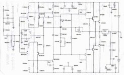
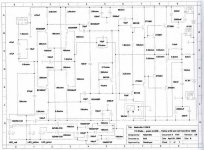
This amplifier is a Brazilian made Nashville unit.... i assemble and i am still using....but i fell something strange with the bass... i think it is precise... to much to my personal taste.... so if you can make it better, or different , in bass response....please, let me know.
This unit was made around a thousand.... now a days is still driving "trio eletrico".... electric trio is a truck band.... a mobile music machine.... Scania Vabis heavy trucks, 10 amps inside, air conditioned, 50 speakers surround truck... upside the musical instruments, microfones, switchers, mixers and all samplers and is making parties around this country.... two states visited in a month.... all the country knows them very well an Coke is the owner of the bigger one!.....heard by more than 150 milion citizens that lived in big towns.....others in jungle!
So it is hardly tested..... may have a mistake in schematics, this unit is made early seventies....1978 to be precise.
I have multisim....but i do not trust entirely on it.
Many thanks in advance the attention and time spent with me.
Carlos is the destroyer X
Attachments
Complementary informations
I use 45 volts plus and minus..... normally this unit uses 62 plus and minus.
The input attenuator can be supressed..... is already cutted!.... input in 1K5 resistor.
Output impedance used is 8 ohms
Transistor with a floating 1K8 resistor is TIP41/TIP42...... the following transistor is also the same pair...... the output i used 2SC2922 and 2SA1216 by Sanken..... TWO PAIRS.
Factory used transistor metal can transistors alike 2N3055..... was some MJ models.... i do not remember 15004 and 15005...not sure.... a complementary heavy unit.
Those Sanken is around 250 volts maximum, 16 amperes maximum and 150 Watts maximum heat transfer..... gain is around 130 for NPN and 140 to PNP (my units).
Do you think a bias multiplier... a transistor to controll the bias will be better?..... Why?
Diodes is inside heat sink.... all them from bias.
If i forgot something, please, let me know.
Carlos
i am just a beginner, so what i say might be stupid (so forgive me ") ) i dont get the point of this amp..if youre going to go to the trouble of having mirror Diff pairs..why not have active current sources and current mirrors?...
) i dont get the point of this amp..if youre going to go to the trouble of having mirror Diff pairs..why not have active current sources and current mirrors?...
wouldnt it also be more desirable to have a cascode connection for the VAS
also what is the point of having a diode Vbe???...why not use the conventional transistor Vbe multiplier?...just a thought..
) i dont get the point of this amp..if youre going to go to the trouble of having mirror Diff pairs..why not have active current sources and current mirrors?...wouldnt it also be more desirable to have a cascode connection for the VAS
also what is the point of having a diode Vbe???...why not use the conventional transistor Vbe multiplier?...just a thought..
... as you are suspecting errors in the schematic: I feel the 22pF at the lower transistor of the VAS should be placed from base to collector instead of base-emitter…
Also I am hoping that you use the C-types of the TIP 41 etc.
A and B types will struggle with voltage rating.
http://pubpages.unh.edu/~aperkins/pdf/TIP-devices/TIP41.pdf
As you run the circuit with 45V instead of 62V all your biasing will be less
Than in the original design. You could come closer to the original if you decerase both 56k (from differentials to rails) down to 47k or 39k.
Please note this will also affect the bias of the output stage…
Possible improvement of PSSR, may result in improved hum, if necessary:
You could split the 56K (well or whatever you chose 47k…39k) into two
series resistors.
I.e. 10K to the rail + 33k towards the differential. From the center of both resistors
put 100uF to ground. So your bias of the differentials will get rid of the supply hum/noise.
Best solution of course would be to use some decent current sources instead of a simple resistors.
Next point is the bias of your output transistors:
I have doubts that the green LED + 3 diodes will compensate the temperature drift of the 2 x 3transistors = 6 diodes = 12mV/°C.
Also the bias level itself might be low or zero?
Zero would explain that you have no issues with temperature stability of the bias of the output transistors.
Which bias current in the output transistors do you measure.
…which values of emitter resistors do you use for your Sanken types and which DC voltage drop do you measure across each emitter resistor?
If this bias is to low, you will have a big influence on the sound.
Suitable values are 50 mA per pair of transistor.
If you have two pair this will generate about 2W constant losses in each transistor.
….makes 8 W losses in a Mono amp, 16W for stereo….
If you fear to design and adjust a bias multiplier, you could try this approach:
Pick 6 TIP41. Use each of it as a diode, simply by connecting the base to the collector. Then connect these “diodes” in series. This series connection of 6 diodes must be mount on the heat sink. This diode assembly would replace the series connection of the green LED and the three 1N4148.
Now try to adjust a proper bias by testing different values of the emitter resistors for the sankens. BUT BE CAREFUL. You should start with high values for the emitter resistors! May be around 2 Ohms for each Sanken. Then measure the bias current and adjust the resistors so that you get a reasonable bias current and keep observing the temperature of the heat sink…..
A bias multiplier would probably enable you to adjust the bias more comfortable and enable you for lower emitter resistors. But the lower values you will use for the emitters, the more accurate your adjustment and temperature compensation must be.
…lot of good opportunities to burn the expensive SANKENs during this….
Why is a proper bias necessary?
Without bias the output impedance of the amp will be very nonlinear for small output currents, resulting in high crossover distorsions.
For proper current bias of the output stage, you typically give a DC bias acrross the basis inputs. This DC voltage bias must give the base-emitter-voltages for the output stage ... + some millivolts more which you will see across the emitter resitors. Temperature compensation of this bias is very important, because some millivolts more DC bias voltage at the basis inputs of the output stage will give also some millivolts (little less than at the basis) across the emitter resistors. If you now have low values for the emitter resistors then, some millivolts will already make a remakable change in bias current......
Good Luck
Markus
Mr Markus, The chocoholic
Markus..... here is the new schematic..... include VBE multiplier.... i forgot to put the condenser between 39K resistor that is in the first stage base..... i will divide this resistor in two unit the way you said.... 12K plus 27K...... and a condenser from those resistor junction to earth.
You will see a 470 Microfarads Condenser without effect...near the audio signal generator (virtual)..... left side and up the schematic..... i will not use it.
Please...let me know if you find something else.
In a week i will fix everything and tell you what i "feel" related to sound changes.
Carlos
Attachments
Hi Carlos!
I think you got my points.
Just two further thing which I noticed:
- The transistors of the VAS with the 22pF are shown as BC546
and BC556. BC 556 and BC546 are 65V types, but in the application they may see up 90V (+/-45V... full swing). So I am quite stunned that your amp works since years with such underrated transistors. I would expect 100V types or higher in the VAS. Especially if I think that the original amp was running with more than +/-60V, I would expect 150V types..... ???!
- Your bias multiplier shows 390 Ohms + 2700 Ohms from base to collector and 47 Ohms between base and emitter.
The idle current of the VAS may be between 4mA and 5mA, this
will not match to the resitor values of the bias multiplier.
Your transistor of the bias multiplier will remain turned off and allow
a horrible high (and probably destructive) bias for the output stage.
If you have about 3000 Ohms between base and collector then
suitable values for the resistor between base and emitter would be
around 500 ohms... 600ohms. I would propose to use 560 ohms and split the resistor from base to collector in 1.8k fixed resistor plus 1.8 k potentiometer. For first turn on you should put the potentiometer to 0 Ohms. This will make the transistor of the bias multiplier conductive and result in nearly no bias current of the output stage..... Then you can slowly increase the value to the desired value.... hope this works, it is just some rough estimation by hand!
Good Luck and thanks for the infos about the insight of the SANKEN!
Markus
12k + 27k + 100µF:
This should act like current source, which delivers around 1.1mA.
(45V-0.6V) / 39k Ohms = 1.1mA
The dynamic resistance of this current source at audio frequencies will be around 27k (seen from the emitters of the differential). Without 100µF it would be 39k.
The resistance of this current source is mainly influencing the common mode rejection of the differential, but should not cause flaws in frequency response.
You can also try 39K (towards emitters)+ 1k (towards rails) + 100µF. Improvement against rail hum/noise will be less (lower PSSR), but common mode rejection will become better again.... a traditional trade off, where you can vary according your taste.
Of course an active current source with a transistor could serve all this even better, but normally it is not necessary. And I love simple solutions..
Bye
Markus
Lots of thanks Chocoholic
Thanks a lot...... i also prefer simple solutions.... take a look the amplifier i put...... saying i use darlingtons....... this amplifiers beats the one you helping me improve or update..... i am finishing one of this i talking about with two channels.
Using one just one channel..... speaker under my bad to bass...with a input filter to "only bass" passing .....other amplifier, stereo use TDA7264.... 10 plus 10 clean medium frequencies..... and another one TDA7265, almost the same, but worst bass frequencies is driven two twetters... very well positioned .
The difference i felt is because my bed have some place to put videocassetes and audio cassettes old tapes.... and the one we improve..... putting 100 watts do not shake cassettes.... and the one i put with darlington, a TA-F30 old Sony put them to shack the way i had to remove cassettes from their place under the bed.
This TA-F30 is old and simple...no CCS..... a simple diferential circuit..... one current (or voltage) stage and output...... people that heard the other one and now is hearing this one tells me this is better.... the Sony simple and used design for 10 year by a lot of manufacturers..... a Universal easy amplifier....Mr Elliot makes something similar and also very good....Rodd Elliot... i like him!
This way, i think i like distortions.... or something alike, because this one we improve is a very well accepted unit hear in this country..... it is very respected.... so i stay confused and checking for mistakes and improvements to compare them again.
thank you..... i will read slowly and carefully..... i do not read this way now, because i cannot....latter on i ill put a message.
Carlos
I have donne all the mods you told
And the amplifier became better.... bass is different..... and stay precise but alike "warm"...... i like it.
Medium frequencies.... female voices turns more clear.
Quality increase.... easy to feel that's now is another amplifier!
I will call friends and test with them.... also i will spend a lot of time hearing some musics that i use to test...i do not know the names....also what the people says.... i hear only sound....a different way.
Also i will compare with Sony TA-F30 with the strange bass that i like.
Something interesting....new STK Integrated audio power Chips.. smaller, reduced size 65%.... price i do not know, is using this circuit inside.... the same as Sony TA-F30.... may be price.... or they discover some people likes that kind of sound.... take a Look in Sanyo....model now if i remember is STK420-020 (this puts out 20 watts rms.... stereo unit)....... goes to STK420-120 with the same kind of schematic.... very small differences.
The same way those people in Broadcasting TV looks into a monitor... they are watching color phase, syncronism.... black level.... video level...noise....sparks.....and other deffects.... they do not know what is happening in the image... if someone speak this or that and if was a man or a woman in the video sequence he put his attention.... same way Ginecologist.... checking technically....a different approach.
I suppose audioholics do that all the time or part of the time.
Many thanks your help........ sorry poor english....but was helpfull.
Carlos

Thank you...now this amp have you inside
Yes..... like your soul.... it's your creation, because changes are great!
One more good thing you made in this life.
I will return directly to your mail in a matter of 4 to 5 days with some comparison results.... but better it is related the way it was before you told me things to do... related to sonic improvements ...no doubts!
Thank you....danke!
Carlos
My conclusions Mr Chocoholic
I and my friends conclude that the amplifier becames real better....but some of them prefer this one you modified..... some others prefer the Sony TA-F30 that i like to reproduce bass.
The Sony's bass is imprecise..... your mods amplifier, old Nashville real improved, good bass, precise, but do not long the way i like..... some bad controled decay...... bass going out slowly and new tone of bass coming.... so.... if i can translate in words......
bumbombum is the Sony..... the improve is bum bom bum.... there's a space without bass.... perfectly normal related to sound source...fidelity....but i like the unfidelity of the Sony..... related to highs no way to compare..... your unit is explendid... this way, thanking you again and again.... i will use "your" machine as twetters drivers.... i will increase a little impedance.... i will put some off them in series to make 12 ohms..... also 12 ohms resistor in series...... 10 microfarads condenser, considering the increase of impedance in output.....and this way gonn'a work.... i normally install 22 ohms serial with 22kpf in our speaker i have.... thats to control eventual oscilations.... but i control to not increase too much when parallells sometimes ading big capacitance values and lower resistance values.... i take care of it.
Now i decided to construct JLH, class A, stereo, to voice.... and increase Sony power to 70 RMS plus 70 RMS/ 8 ohms
This way i will use "your" amp to highs
The JLH, last model that you find in our forum. to Voice, medium
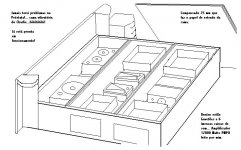
And to bass, imprecise and strange, i will use the increased power Sony old machine.... take a look my sound bed... full of speakers... some of them home made..... vibration is wonderfull.... in front, 4 meters.... twetters....... both sides i have medium range speakers
I thank you... a lot of hot chocolate for you!.....lets see..... with cashew nuts mixed, in pices to chocolate bar....inside, a cream with the taste of "Chantilly" cream.... wipped cream... do not know the name in you language.
I and my friends conclude that the amplifier becames real better....but some of them prefer this one you modified..... some others prefer the Sony TA-F30 that i like to reproduce bass.
The Sony's bass is imprecise..... your mods amplifier, old Nashville real improved, good bass, precise, but do not long the way i like..... some bad controled decay...... bass going out slowly and new tone of bass coming.... so.... if i can translate in words......
bumbombum is the Sony..... the improve is bum bom bum.... there's a space without bass.... perfectly normal related to sound source...fidelity....but i like the unfidelity of the Sony..... related to highs no way to compare..... your unit is explendid... this way, thanking you again and again.... i will use "your" machine as twetters drivers.... i will increase a little impedance.... i will put some off them in series to make 12 ohms..... also 12 ohms resistor in series...... 10 microfarads condenser, considering the increase of impedance in output.....and this way gonn'a work.... i normally install 22 ohms serial with 22kpf in our speaker i have.... thats to control eventual oscilations.... but i control to not increase too much when parallells sometimes ading big capacitance values and lower resistance values.... i take care of it.
Now i decided to construct JLH, class A, stereo, to voice.... and increase Sony power to 70 RMS plus 70 RMS/ 8 ohms
This way i will use "your" amp to highs
The JLH, last model that you find in our forum. to Voice, medium
And to bass, imprecise and strange, i will use the increased power Sony old machine.... take a look my sound bed... full of speakers... some of them home made..... vibration is wonderfull.... in front, 4 meters.... twetters....... both sides i have medium range speakers
I thank you... a lot of hot chocolate for you!.....lets see..... with cashew nuts mixed, in pices to chocolate bar....inside, a cream with the taste of "Chantilly" cream.... wipped cream... do not know the name in you language.
Attachments
My conclusions Mr Chocoholic
I and my friends conclude that the amplifier becames real better....but some of them prefer this one you modified..... some others prefer the Sony TA-F30 that i like to reproduce bass.
The Sony's bass is imprecise..... your mods amplifier, old Nashville real improved, good bass, precise, but do not long the way i like..... some bad controled decay...... bass going out slowly and new tone of bass coming.... so.... if i can translate in words......
bumbombum is the Sony..... the improve is bum bom bum.... there's a space without bass.... perfectly normal related to sound source...fidelity....but i like the unfidelity of the Sony..... related to highs no way to compare..... your unit is explendid... this way, thanking you again and again.... i will use "your" machine as twetters drivers.... i will increase a little impedance.... i will put some off them in series to make 12 ohms..... also 12 ohms resistor in series...... 10 microfarads condenser, considering the increase of impedance in output.....and this way gonn'a work.... i normally install 22 ohms serial with 22kpf in our speaker i have.... thats to control eventual oscilations.... but i control to not increase too much when parallells sometimes ading big capacitance values and lower resistance values.... i take care of it.
Now i decided to construct JLH, class A, stereo, to voice.... and increase Sony power to 70 RMS plus 70 RMS/ 8 ohms
This way i will use "your" amp to highs
The JLH, last model that you find in our forum. to Voice, medium
And to bass, imprecise and strange, i will use the increased power Sony old machine.... take a look my sound bed... full of speakers... some of them home made..... vibration is wonderfull.... in front, 4 meters.... twetters....... both sides i have medium range speakers
I thank you... a lot of hot chocolate for you!.....lets see..... with cashew nuts mixed, in pieces to chocolate bar....inside, a cream with the taste of "Chantilly" cream.... wipped cream... do not know the name in you language.
Attachments
Hi Carlos!
....no need for thanking me so much...
I am just posting what comes to my mind, and I
am also learning from the replies here....
Thanks for the hot chocolate!
A cyber chocolate will not impact "project ADONIS"
...bed with speakers....
I did some tests, because I was thinking about a "tumult seat" (...thread..).
I came to the conclusion that this is nice, ....but just for 10 minutes!
If I listen to music this way for a longer time, even decent songs push me up and after a while I do not feel comfortable any more.
So I am going for a normal subwoofer with two SADHARA drivers
and replace my 11x Dynaudio ESOTEC 15W-75 sub.
(also described in one of my first threads here.., cannot remember the name of that thread... something with "tiny subwoofer..." )
The small Dynaudio woofers then may be used in small but accurate 2 way systems.
...work for the next years, as I a do not find much time for this....
Cheers
Markus
- Status
- This old topic is closed. If you want to reopen this topic, contact a moderator using the "Report Post" button.
- Home
- Amplifiers
- Solid State
- Please,can you improve this amp, let me know how