Hello,
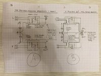
Here is how the internal ground loops in a stereo amp can be solved. Please disregard comments in the drawing, as they refer to another matter.
Case A - this is usual amp wiring, which suffers of hum
Case B - this wiring brakes internal ground loops - the hum is gone. However this is at the expense of increased distortion due to the distant ground sensing by the feedback loop.
The radical solution to both hum and distortion is to use local feedback ground sensing like in the Case A and then supply each channel from independent, galvanically isolated power suppply.
Attachments
Last edited by a moderator:
Some good stuff on this thread.
The twisted power and speaker cabling are good at reducing loop areas which are directly implicated, along with common impedance coupling, in noise/hum pickup.
It’s also important to consider overall loop areas related to how you route the internal wiring in an amplifier. I’ve added a few more slides to the ground loop presentation (link below) to discuss this point along with some tips relating to toroidal transformer positioning for minimum noise/hum.
One other point re input connectors. I recommend they are located next to each other and the signal grounds are bonded together. This traps cross channel ground loops inside the amplifier and if you then take care with your internal input cable routing to minimize loop area, you can get hum levels down to very low levels ( < -100 dB and better).
bonsai,
Indeed, the input connectors should be placed close to each other. Also the input cables should preferrably be binded in order to reduce the inductance loop area. There is one other effective solution to the hum problem - differential sensing. Works like a charm. This is what I use to make my amps dead quiet and insensitive to ground loops.
jarema
 I've deleted jarema's original post and edited the second to put the original text with the image (as the bad image was causing a big delay opening the thread). I deleted my posts as they were no longer necessary.
There’s a lot of discussion about where to connect the speaker return - method A back at the amplifier module (and from there to the PSU with the common module 0V line) or method B directly back at the PSU 0 V.
Clearly in methode B , you avoid putting large signal related currents down the common 0 V line while in the first, you can minimize the loop areas.
In the methode A approach, you can mitigate the issue by making sure you have very good decoupling on the module. This traps HF currents on the module PCB (short loops between local reservoir caps, OPS trannies and twisted capable to speaker load) leaving only LF currents in the common 0 V line between the module and the PSU. If you are seeing much higher distortion using method A, it’s a sure indication that you don’t have sufficient local decoupling, or, you have a common impedance coupling problem on your amplifier module.
In the first approach, run the speaker return cable alongside the speaker hot cable and then around the amp module and continue alongside the 0V line back to the PSU to minimize the loop area.
Onward and upward
Last edited:
seems you haven't got me right. Scheme B reduces hum, but may increase distortion. Scheme A reduces distortion, but makes the design sensitive to hum (unless separate power supplies are used). Hence, we do not have any controversy here - I do agree with your points
I think we all agree on that.
The tough questions arise when we have to compromise with a common supply, in a single enclosure. Hum breaking resistors basically are another compromise, between case A and B, balancing hum and distortion.
Then there's the issue of earthing and mixing gear with varied earthing schemes through unbalanced interconnects.
The tough questions arise when we have to compromise with a common supply, in a single enclosure. Hum breaking resistors basically are another compromise, between case A and B, balancing hum and distortion.
Well said. Every way to wire such an amp is a (different) compromise. It is possible but tough to find the compromise that fits your personal preference in your specific setting (the output impedance of the signal source, characteristics of the wiring, cables, etc.); it is even tougher to come up with a universal recipe, which is why there are so many discussions on the topic.
It is always a compromise because, with the non-inverting topology and a single ended input, there is no right way to wire the amp, not even one mono channel. For the topology to work correctly, three points must be one and the same (separating them with wires is a compromise):
- The ground connection of the speaker
- The ground end of the feedback network
- The signal source's ground
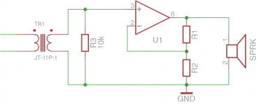
One good but expensive compromise is to use an input transformer such as the JT-11P-1.
Attachments
The two biggest issues in wiring up an amp I have found are
1. Common impedance coupling - a few solid rules wrt PCB layout and power supply hook-up can all but remove this problem. The most important rule is do not let signal returns and power supply 0V (decoupling or the main PSU 0V) share common traces on a PCB
2. Loop areas - this is often the most difficult problem to contend with - and covers normal ground loops, cross channel ground loops and what I would call 'signal' loops
A good technique on #2 above is to draw a picture of your physical layout and then shade in the area bounded by the power cabling from the PSU to the amplifier and the input connectors. You want to minimize this area as much has practicable and this is done by correctly routing your cabling
HBR's are a powerful technique for reducing cross channel ground loops. I have found the best way to deal with this is to locate the input receptacles right next to each other and bond the input grounds together (but make sure they DO NOT connect to the chassis at this point!). You then run the input connector wires to the amplifier modules TOGETHER, with one of the channels then going on its own to the remaining amplifier module. You still use the HBR because it dramatically reduces any cross channel ground loop current arising in the amplifier. The reason you bond the signal grounds together at the input connectors is to trap the ground loop currents inside the amplifier. If you do not do this, the cross channel ground loop current flows out through the interconnect shield, through the ground connections into the source equipment (where you may well also have cross channel ground loop issues) and then back out along the other channel shield.
I usually use 15 Ohms for the HBR and have not found any issues.
I'll try to put up some measurements in the next few days to show how these techniques can deliver good performance even though the mechanical and electrical construction may be quite complex.
In my ground loop presentation I also show how to use a pair of headphones as an 'audio scope'. If you amp is quiet on a pair of 90dB/mW headphones, it will be silent on a normal speaker. Once you are at that level, a sound card can help to get below this (but if you don't have one, the headphone trick will get you pretty close).
One thing I learned about killing 'hum' is that you never stop learning!
There is no end to it, because there is no way to make it 100% right.One thing I learned about killing 'hum' is that you never stop learning!
The difficulties stem from the complicated nature of "ground". It has at least four different roles:
- Safety ground - protects humans touching exposed metal parts in case isolation fails
- EMI shield - encloses our device(s) and interconnects and prevents EMI ingress
- Current return - serves as a return path for all kind of currents, both DC and AC in the frequency range of interest
- Common voltage reference point - the "zero volts" reference shared across multiple circuits and boxes by various signals, both DC and AC in the frequency range of interest
Last edited:
You have to separate out the items:-
1. Safety ground - goes from the mains inlet receptacle to the metal chassis. The amplifier ground - at the junction of the reservoir capacitors - connects once and only once to the same place as the safety ground (because you do not want loop currents flowing in the chassis)
2. EMI/Shielding - make sure where your input connectors come into the chassis, they are coupled to the chassis at the point of entry with a 1-10nF ceramic capacitor. The connector grounds themselves must not make contact with the chassis otherwise you get a ground loop - the input grounds should go to the amplifier module and not directly back to the main power supply in order to minimize loop area. The 1-10nF capacitors between the connector ground and the chassis ensure that at RF the cable shield, the receiving amplifier and the source (e.g. a preamp) appear as one housing.
3. Current Return Path (e.g. main 0V from PSU to amp modules) - do not mix signal and decoupling/power grounds on the PCB. Ensure good localized decoupling on the amp modules to trap HF currents on the amplifier modules and in the location of the OPS. 220uF to 1000uF right at the output stage and close to the incoming +, - and 0V module supply is about right.
4. Common voltage reference point - more often than not, if you follow good grounding connection practices ('T' off from the reservoir capacitors, speaker returns closer to the 'T' than the 0V supply to the modules this wont be a problem). However, sloppy cable routing between modules, failure to twist power supply wires (on AC and DC side) and failure to use decent screened cable (or twisted wires) for signal connections will cause problems.
As mentioned earlier, a good technique is a physical layout with lines shown for the interconnects between the amplifier modules, input connectors and the power supply. Shade in the area bounded by the power supply wiring and the input wiring. This is the 'ground loop area' in your amp - you have to get rid of it (i.e. make the area as small as possible) through cable routing. Once you get the hang of this, you will be surprised at how quickly you can take a 'noisy' amp to absolutely silent.
For me, the takeaway from ilimzn's posts is that ground loops are an unavoidable fact of life, esp. if you consider more than one box.
What surprises me is how little it takes to make ground loops an audible and measurable problem. Say, you have a power amp with the gain of 26dB (20x V/V) and want to have no more than 0.01% THD+N at 1W into 8ohm - a reasonable target for 21st century. 1W into 8ohm means ~2.8V RMS across the load or 140mV RMS at the input. 0.01% of 140mV is just 14uV, or ~1uA through a 15ohm GLBR.
One can hope that following good grounding practices will keep ground loop effects at a microvolt level. A better option may be not to rely on a single reference point for all signals.
Last edited:
Yes, although I think the loop via mains earth is easier solved than others, cross channel being harder especially with multichannel amps, though, again hum breaking resistors solve that problemHe was certainly thought provoking wrt earthing the enclosure and how to wire the ground loop breaker.
Yes, although I think the loop via mains earth is easier solved than others, cross channel being harder especially with multichannel amps, though, again hum breaking resistors solve that problem
The best weapon against cross channel ground loops is sensible cable routing plus HBR, keeping the input connectors together and bonding their signal returns together at the point of entry into the housing and using bonded (i.e. dual) interconnect cables.
- Status
- This old topic is closed. If you want to reopen this topic, contact a moderator using the "Report Post" button.
- Home
- Amplifiers
- Solid State
- The dozens schemes to wire an amp...