That's not safe, the chassis must be connected directly to protective earth (unless it's Class2, double insulated)
Read what I said, AND the actual regulations carefully.
If there is NO earth connection, the device must comply with class 2 doublke isolated power supply (denoted by a square within a square symbol).
If there is an earth connection it is not necessary that the chasis is directly connected to it, it IS necessary that the cable MUST have an earth wire.
What is necessary re chasis connection to earth is that the connection such as it is must simultaneously withstand a current sufficient to blow the breaker AND while doing that must prevent the touch potential from being higher than the regulations state (when I was going through EE state certification this used to be maximum 48V and has since been reduced to 24V maximum DC or peak, at least in the EU).
So as I said, it is a good idea to read the regulations past the paragraphs that apply to kettles, heaters and washing machines, because those do not get interconnected with other kettles, heaters and washing machines via interconnect cables carrying an audio signal. Further paragraphs and rules give several recommendations on breaking earth loops and electrical conditions that must be satisfied for the method to pass certification.
This is why I said that an earth loop breaker must be inserted between the case and the earth line, not 'nothing'.
It's simplest form is two diodes anti-parallel plus one resistor in parallel. The diodes must withstand blowing a 16A breaker (in some places 20A) at least in the EU. Probably more in the US. This is actually not a great problem and even a 5A regular diode will do it and survive. The diodes also limit the maximum touch potential to about 1V under normal circumstances. Under those, it is expected that breaker melting current will never flow because (at least in my country which has fairly recently joined the EU) all house installations built after 1988 are required to have a differential and ground current protection breaker, which will disable the installation if the current through the live line is not equal to the neutral line, or there is a current in the earth wire. All of these are detected on the order of mA. The 'burn the breaker' regulation is a legacy requirement for installations that are older.
Not reading and understanding the regulations often leads to situations that result in exactly the opposite of what the regulations are supposed to insure.
For instance, using a mains filter usually means that the earth wire has capacitors between it and the live as well as the neutral mains wires - one each. This works well if there actually IS an earth wire in your installation. At some point (between 1970 and 1988) the regulations here changed so that every socket has to have an earth contact. As a result, today you can't even buy one without it (so called schuko in Germany, most EU countries inherited the concept if not the exact for of plug and socket). However, that means that in older buildings there are sockets with no earth, even if one appears to be there - for instance when the original socket broke and there was no option to replace it with one with the earth contact, that is however not connected anywhere because there is no earth wire.
When a earthed mains filter is connected to such a socket, the two capacitors form a capacitive divider which puts the metal case of your equipment at half the mains potential, 110VAC referenced to a 'real' earth potential. Have you ever felt that passing a finger along the edge of such a box gives you a vibrating sensation accompanied by a very mild electric shock? Well, with a sufficiently large filter and moist hands, it will NOT be mild.
There are more examples. For instance connecting a cable TV box might put the potential of the shield of the cable connection at tens of V difference compared to your earthed equipment you want to connect it with, because it may be connected to an 'earth' which is actually a neutral line miles away, with the voltage drop between that point and your 'earth' (also locally connected ultimately to the neutral line) in tens of V and low impedance. Even trying to connect the cable while touching the metalwork will give you a proper shock - and it's all done according to regulation. In large and distributed PA systems, such errors can lead to equipment failure and even cable fires as a ground line attempts to carry part of the neutral line current between distant points with a large difference in potential due to voltage drops in the mains network.
While simple earth line breakers will not solve the problem, my point is, the introduction of earthed IEC connectors to audio has been one of the biggest pitfalls ever(*), leading to insidious and often invisible problems. My recommendations would be to revert back to old rules when components were class 2, double isolated. If you need to have the system earthed (which I really don't know why) do it on one component only, preferably integrated amp or preamp where all interconnects meet.
(*) You might have noticed that the 'cablemania', i.e. attributing huge differences in sound to cables (including mains cables) and a whole associated flourishing industry started about the time 3-pin IEC connectors were introduced to audio equipment that was previously almost as a rule class 2.
If one thinks about it, it's no big mystery. Since the ground is connected to the components' case, as is usually (and as I mention above, due to incomplete regulation interpretations) the earth wire on the power cord, the most basic rule of signal transfer through standard unbalanced interconnect cables is violated - the forward and return currents must always be exactly equal. Instead, if you look at the actual situation, the forward current travels through a wire connecting RCA central contacts, while the return current travels through the wire connecting the outer (ground) contact AND EVERY EARTH WIRE in the system in all possible combinations. These also contain other currents, because there are multiple single line paths which are not co-located, so some can pass next to power supply wires, speaker wires, transformers, etc etc with all sorts of crap being induced in them, part of which is now also going through the ground on your interconnect cable.
Is it a wonder that under those circumstances EVERY cable you change will result in some audible difference - do not be fooled by how minute the actual current balance changes may be, you should look at it on a log (dB) scale, and that reveals a whole bunch of horrors. So, instead of doing things properly (and what that is, becomes obvious if you actually draw the current loops in question) now we are at a point where people say a fully balanced interconnect is the way to go even if you connect two components 30cm away from each other. It goes so far that certain very high end and expensive manufacturers have introduced their own balanced line standards, where a 10k terminating resistance on the receiving end is considered unusually low (never mind the original spec was 600 ohms...).
Please do not propagate the madness further. Some manufacturers have figured this out and are taking measures that still comply with the average audiophile expecting an IEC cable if the component is to be deemd a decent one. Rotel in particular uses IEC connectors without the ground pin, for exactly the reasons stated above - getting class B isolation approved is really no problem, transformer manufacturers usually don't even produce non-compliant transformers.
Last edited:
And again they suffer from noise voltage appearing along the "GND breaking resistors" which is appearing 1:1 at the output voltage. Assume a 100mA balancing current into a 10R isolator, this will add 1V of noise at the output!!Two other schemes.
Also in the first scheme, the long load current return from amp to psu GND is prone to pickup magnetic field, and especially offending is the recharge current pulses in the corresponding supply lines. Those three lines are twisted but when the speaker return runs close it might still pick up noise...
This all still may end up at "OK levels" of noise reduction for most purposes but "GND breaker resistance" is a fundamentally flawed concept. With only a little more effort a standard balanced input can be built where voltage drop and current flow on the GND line is allowed but cancelled out by the diff amp.
Two other schemes. One is based on Cordell's book. Speakers return to PS, zobel at input/output.
The second is hifisonix's. Speakers return to amps pcb, ground loop breaker.
If I understood Mark correctly (a caveat for all schemes btw, correct me if I've misrepresented someone's position), it would be close to his, but with 1R HBR (+ diodes across the HBR) and a resistor in // with the groundloop breaker ?
Edit: I explicitly added the input rf filter to the amps this time.
Edit: we're missing AndrewT on this thread. Maybe would I have finally been able to put into a schematic exactly what he meant with his MAG.
The second one is the better option.
You have two problems to solve with the wiring:
1) Local loop that happens because your single supply for two amps has to split it's ground into the left and right grounds, which then get connected together on the source side. Since there are two paths, one from PCU ground to source through the left and the other through the right amp, you have loop. Whenever there is more than a single path from two points, you have loop(s). This loop will get stuff induced by what is inside the amp enclosure and also what is inside the outside portion of the loop, formed by the ground wires in your interconnect cables. Keeping L and R cables together will minimize the area of the loop and thus problems in that part (and now you may realize why old style RCA interconnects used the L and R wire stuck together side by side).
2) Earth loop(s) formed by the earth wiring from each component to a common earth point - because the components are now connected with earth wires to common point, but also between each other by ground which is normally connected to earth internally.
In case 1, you can do a lot topologically, i.e. where you actually route wires. Still, the only way to break the loop which is unavoidable in this case, is to add loop breakers between signal and power ground. Why? Most of the current induced here will be from resistive drop of the speaker return current (actually difference between L and R channel speaker current) and any inductive component, induced eg. by the transformer stray field. Do not underestimathe the second one, you are basically making a fairly bad 'transformer' between the transformer windings and the loop, but the loop is ONE turn, so even with bad magnetic coupling you are getting a fairly large ratio of windings in the transformer and the single turn loop, so it's inducing a low voltage but with lots of current capability.
In your second picture, the speaker return is from the local power decoupling, so most high frequency current will flow from there, meaning the lower frequency components will go from the main caps. BUT this will then act mostly with the wiring resistance, so voltage drop will be reduced because the inductive impedance component of the wire impedance will be low for these low frequencies. This will reduce the voltage difference between the L and R power ground to begin with. The resistors between the power and signal ground will be very large compared to the impedance of the wires between the power ground and Psu ground, so a very miniscule current will flow from one signal ground to the other, resulting in a very small error signal injection into L and R signal ground. Look at it as a bridge circuit made of resistors. Since the 15 ohm resistors will on average be about 1000 times higher in impedance than the ground lines, the voltage difference between the signal G will be that much lower than between power G, so it's a factor of -60dB reduction. This will however be amplified by your amp, by about 20dB or so. To cut a long story short, it means the signal separation is reduced by about 40dB from 'ideal' but also that much improved from the start of the thread!
Also, any induced current is also reduced by an even larger value, as for it the 15 ohm resistors between power and signal grounds are in series, so it's influence on the input will be back to ~60+ dB lower than at the start of the thread.
For case 2, similar rules apply. In this case the reduction is smaller because of the 1 ohm resistor. However, in this case also the touch potential security rule MUST be satisfied. Hence the two anti-parallel diodes. They will limit the voltage between ground and earth to 1V. However, they also make it possible to significantly increase the resistor. This is because they are fairly high impedance as long as the voltage difference is low, so if the resistor is also a high value, the loop current will be very low and not contribute much. However, now you have more wiring in the system and connectors, so the resistance of the wired part of the loop is not as low as soldered wires in your amp, it may well approach a fraction of an ohm. Since that becomes a part of a voltage divider with the resistor and diodes, and it is where the error voltage is produced, it is prudent to keep it as small as possible in comparison to the resistor and diodes so that the voltage drop is a small as possible on that part of the loop and most of it is at the resistor and diodes where we don't care. Therefore the resistor will have to be tens or perhaps low hundreds of ohms to get about 40-60dB reduction in error from that loop.
Since under normal operation it's just the wire loop, the actual voltage is in the mV range. If a fault occurs, the current and/or voltage may rise and here is where the diodes come in, as they start conducting, their impedance falls exponentially, until they are the ones carrying virtually all the current. This action limits the potential between earth and chasis to about 1V in case of a fault, well below the 24V regulatory (and common sense) requirement.
To ilimzn. What are Class 2 and B? Are these EU standards?
Class 2 (sorry, not class B) is a class of mains fed electrical device according to many (incl. EU) state's regulations. This is a device that has no earth wire (commonly stated) but the proper statement is 'no explicit protection from touch potential', i.e. they rely on isolation do that the user can never end up touching parts that are at mains potential. It may be a mechanical barrier or non-conductive case material (such as mains powered beard trimmer or kettle or kitchen mixer), or a transformer system where the primary is again isolated from any secondary or exposed circuit in such a manner that the user cannot get in touch with it from the outside of the device. In all cases, it should be constructed so that a fault of reasonable kind maintains the isolation (eg. if you use a hammer to smash it specifically to get to the mains wires' it's your fault) for instance the mains cable and part where it might go into the metal enclosure of the device is constructed so that you can't abuse the cable to make it's wire contact the metal, before the wire itself breaks off.
Such devices usually have a symbol on the declaration panel that looks like a square with another square inside it, denoting symbolically a 'double barrier' from the mains potential.
Class 1 devices use the metal case as a shield from the mains potential by tying it to a 'touch potential return wire' or 'safety return' commonly called 'earth' - and not very accurately because it does not mean it goes into the earth somewhere at your house (in fact in most cases that would be very dangerous if there is also a lightning strike protection on the building).
The 'earth' wire is connected to 0V potential, i.e. ultimately to a neutral wire of the mains. The idea is, if anything with mains potential (which may be mains live and lethal) gets loose inside the device, it is contained by the metal case so that if it touches the metal case, the potential will be shorted to 0V and (originally) burn the mains fuse thus disabling the live mains feed. This is also true if anything in the device generates other potentials higher than the maximum permissible touch potential (the already mentioned 24V) compared to the neutral. i.e. the metal case. If this shorts to the case, the device's fuse is required to open.
In any case, the installation and connection to the safety return ('earth') must guarantee that in case some potential higher than 24V connects to the case, the safety return will limit it to less or equal to 24V, and activate any safety mechanism including a fuse. I am not sure about the new legislation but the old one required full fault current (16A) to flow essentially 'forever' and the safety return not to fail. In effect, plenty of time to burn the fuse
Last edited:
Ilimzin i admire your prefection about electronic knowledge and explanation. You talk about gnd a lot of times also on other forums... Can you please correct 2 pictures or draw your optimal version. I know you are excellent drawer.
So you propose...i had at home 99% amps that are *direct* grounded, just power amp grounded. Dacs preamps, streamer non grounded or grounded trought loop braker?
Thank you
So you propose...i had at home 99% amps that are *direct* grounded, just power amp grounded. Dacs preamps, streamer non grounded or grounded trought loop braker?
Thank you
Example of Why Millohms Matter
Hello All,
This is a great thread, very useful, I wish it was available a year ago when I was designing a pair of mono block power amps (200W / 8 ohms). I know the thread is trying to stick to stereo amps, but I hope this contribution will be useful to everyone.
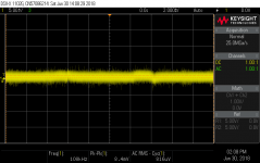
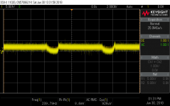
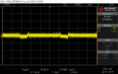
The first scope photo shows the output (4 ohm load) with shorted input for one of the amps. The second scope photo shows the output of the second amp under the same conditions. I spent days trying to track down the source of the 120 Hz ground loop hum in the second amp. For a star ground I use a 6-position barrier block with jumpers across adjacent positions such that all positions are tied together. When I finally arranged the various ground connections on the barrier block for the second amp to be identical with the first amp I was able to reduce the hum significantly, as shown in the third scope photo.
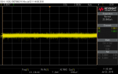
After reading Daniel Joffe’s “The Library of Grounding Problems”, I started thinking about the order of connecting various grounds to the barrier block. With some adjustment to that order I was able to completely eliminate the hum, see scope photo four.
For me, the lesson learned is that milliohms do matter!
BTW, 00940’s schema two, without the input capacitor, is the approach I have used with these two amps.
Cheers,
ceulrich
Hello All,
This is a great thread, very useful, I wish it was available a year ago when I was designing a pair of mono block power amps (200W / 8 ohms). I know the thread is trying to stick to stereo amps, but I hope this contribution will be useful to everyone.
The first scope photo shows the output (4 ohm load) with shorted input for one of the amps. The second scope photo shows the output of the second amp under the same conditions. I spent days trying to track down the source of the 120 Hz ground loop hum in the second amp. For a star ground I use a 6-position barrier block with jumpers across adjacent positions such that all positions are tied together. When I finally arranged the various ground connections on the barrier block for the second amp to be identical with the first amp I was able to reduce the hum significantly, as shown in the third scope photo.
After reading Daniel Joffe’s “The Library of Grounding Problems”, I started thinking about the order of connecting various grounds to the barrier block. With some adjustment to that order I was able to completely eliminate the hum, see scope photo four.
For me, the lesson learned is that milliohms do matter!
BTW, 00940’s schema two, without the input capacitor, is the approach I have used with these two amps.
Cheers,
ceulrich
Attachments
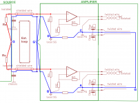
Here is the first diagram from the start of the thread, with the internal loop highlighted.
The loop goes through 6 points, 0-A-B-G and 0-C-D-G.
G is shown as a single point although I have brought a line between the ground ends of the interconnect cables - this will normally be very short, just a metal link between the left and right RCA connectors on the source, usually less than an inch. So, for the purpose of the argument, let's assume it's a single point.
This loop presents two problems.
Problem 1 is the voltage developed between 0-A and 0-C by the load current. The net result is a voltage between A-C that is proportional to the difference between channels.
Sections A-B and C-D are usually very short (a track on the PCB), while B-G and D-G can be quite long (meters) as this is the ground of the interconnect cables. While all of these are in miliohms, it's the relative resistances that are a problem. Because A-B and C-D are very short compared to B-G-D, the voltage developed between A and C appears almost unchanged between B and D. Since B-G and D-G is about equal, the voltage between B and D is about evenly distributed between G (ground of the source) and the ground of the interconnect cable on the amp side - in other words, about half of the difference voltage developed on the section A-0-C by the load currents through this part of the wiring, is added to the input of each channel.
While the voltage drop on A-B and A-C is driving the common ground for the input and the feedback on each channel, the output only amplifies this already comparatively smaller error voltage by the difference in gain between the inverting and non-inverting input referred part of the signal, which is a difference of 1 (non-inverting is -Rg/Rf, inverting is 1+Rg/Rf), so this is not much of a problem compared to the sections G-B and G-D - this error voltage is fully amplified as it appears in series with the input voltage! This will affect the signal separation. Also, keep in mind part of the load current is carried by the PCB tracks and the interconnect grounding!
Problem 2 is the current induced by any electromagnetic field within this loop. This can be really insidious, as it is common (usually for cooling reasons) to put one channel of the amp to one side of the enclosure, and the other channel to the other side, while the PSU and transformer is in the middle. This may put the transformer right inside of the loop, where the loop acts as a single turn secondary for the stray field of the transformer.
Since the loop is a single turn, even with a very bad magnetic coupling, it can develop a lot of current through the loop, resulting in seizable voltage drops even on the miliohm resistances of the wiring. Since the sections D-C-0-A-B are inside of the enclosure and usually present the lower resistance part of the complete loop (interconnects can be quite long!), you can expect most of the voltage drop around the loop to appear on section B-G-D, which again puts half of this voltage in series with each of the source outputs to form the input voltage of the amplifiers. These will then be amplified in full by the amplifiers.
Keep in mind that part of this loop is outside of the amplifier (the interconnect cables) but the induced voltage here will be canceled by the same induced voltage in the live wire in the interconnect. The error occurs due to error current generated only in the ground wires.
Both loops are insidious as they will not appear when the amplifier is cehcked and measured without BOTH inputs attached to a source with a common ground on the source side - the amp will be dead silent and work great with only one channel attached.
Given that when one channel is connected the loop is broken, we may use this idea to implement a deliberate break in the loop. However, we can'e completely separate the ends as we still need a ground reference.
Here's where the 10 or so ohms resistors come in, positioned one each between points A-B and C-D.
For problem 1, the value of these resistors is usually very small compared to the values of Rin, Rf1, Rf2, there will be a small difference between the ground and actual ground reference for the amplifiers, of any difference in currents between Rin and Rf2, but this is normally so small it can be disregarded. The main difference happens because of the voltage drop on the ground wiring to the load, due to the difference in load current. However, this may be reduced by using low impedance wiring and, depending on topological layout, by alternative ground wiring.
While we still get that difference between points A and C, but now it is localized to the output. Because the 10 ohm resistors are a very large resistance compared to the wiring section B-G-D, a very large portion of the voltage difference between A-C is actually dropped on the resistors, and a very small portion on B-G-D, to the point that B-G-D can be disregarded. Typically the difference can be as high as a factor of 500-1000, easily even more if the input connectors on the amplifier itself are brought close together and the grounds connected on them, which makes the section B-G-D essentially appear at the amplifier end of the interconnects and have an extremely low resistance.
Although this will then still be amplified by the amplifiers, the total error signal on the output will be reduced by a factor of ~40dB or so compared to the original picture - usually this will be well below noise and distortion of the amplifiers, hence not so relevant any more.
For problem 2, the result is similar. Again, the critical voltage in the loop is what appears on the loop portion B-G-D. Most of the loop doing the inducing is A-0-C, and again, most of that voltage is dropped on the 10-ohm resistors, so that the remaining voltage B-G-D is very small due to the low resistance of this section.
However, there is a caveat here. One must remember that a part of the loop is outside of the amplifier, the ground parts of the interconnect cables. I have mentioned before that for best results regarding channel separation can be had if the input connectors for the two channels are located close to each other on the amplifier enclosure and the grounds on them connected together with the lowest resistance practicable. This remains true also for the induction problem in the loop BUT ONLY for the inside of the amp. More about this in the next post.
Attachments
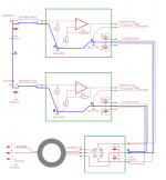
Consider the picture below.
On this picture, the internal ground loop breaking resistors have been added, and the R and L input RCA connectors on the amplifier have been connected together by the shortest practical path (preferably they will be both very close to each other).
There is a similar situation on the source side.
Because of this the connection of the L and R connector is marked as a single point, G on the source side, G' on the amplifier side, these are reference grounds on the source and amplifier side respectively.
While the problem with the internal loop has now largely been solved using the ground loop breaking resistors (between points A-B and C-D), and the input ground point moved to the input RCAs on the amplifier enclosure, to point G', we still may have one problem - the outside ground loop going around through the interconnect cables, from source ground G through the left interconnect to G' and back through the right interconnect to G.
Because the interconnect runs are usually the same length, both sections G-G' have roughly the same impedance. usually this will mean that the current induced in the loop will create the same voltage in oposite directions in the cables, so it will cancel out and G and G' will roughly be at the same potential.
HOWEVER - the same voltage is also induced in the signal wire of the interconnect ('hot' wire) because they circumscribe the same loop path!
While the wires see a low impedance on the source end (usually tens or low hundreds of ohms) the other end is connected to G' via Rin, which is a much larger value, usually 10s of kohms. As a result, each input of the amplifier will see half of the induced outer loop voltage added to the source output, and will amplify that!
It is obvious that in this case there is a clear violation of signal transfer rules through interconnects - current through the forward and return wire must always be equal in magnitude and opposite in phase. This cannot be the case because for the loop voltage the ground wire loop is low impedance, while the signal wire loop is almost open at the amp end.
In this case the only solution is to minimize the loop area and with that any possibility of current induction into it - which is why it is always recommended to RUN L and R INTERCONNECT CABLES BUNDLED TOGETHER!!!! and why old style interconnects had these wires bonded together by the outer isolation.
Attachments
Last edited:
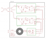
Here is an attempt to integrate ilimzn's suggestions with Mark's, hifisonix's and Tomchr's.
My question is where to connect the secondary ground to the chassis if we earth the chassis through a GLB ?
Second question: if the chassis isn't earthed, does it still make sense to have 1nf caps to chassis from the input rca shields ? Do we need a similar cap across the GLB then ?
Edit: thank you ilimzn for the posts above, they're quite clear.
Attachments
Last edited:
Not reading and understanding the regulations often leads to situations that result in exactly the opposite of what the regulations are supposed to insure.
I'd love to read the regulations. Last time I tried they told me I had to buy them. Awkward. How can they ask people to do what's in the law, but not tell us (for free) what this means?
I'll make it clearer in the next drawing but no, they're isolated. Did I get that wrong?
ilimzn moved the input grounding point to the RCA on the chassis. The caps are required if the sockets are isolated to reduce RF entering the chassis.
You have a big mistake in your last image...10R glb resistors should be connected to local power ground not to speaker ground output connector. Remember, local power ground is the reference for each amplifier and signal ground is generated from local power ground via magical 10R resistors.Here is an attempt to integrate ilimzn's suggestions with Mark's, hifisonix's and Tomchr's.
Here is an attempt to integrate ilimzn's suggestions with Mark's, hifisonix's and Tomchr's.
My question is where to connect the secondary ground to the chassis if we earth the chassis through a GLB ?
Second question: if the chassis isn't earthed, does it still make sense to have 1nf caps to chassis from the input rca shields ? Do we need a similar cap across the GLB then ?
Edit: thank you ilimzn for the posts above, they're quite clear.
The answer will depend somewhat on the mechanics of the amplifier, i.e. what is close to what else, but in general it will be the common point 0 on the schematic.
If the chasis is connected to the common power ground (the point where power ground wires from each channel connect to the common ground on the power supply, point 0) this will also have half the error voltage generated on the ground wiring by the difference in load current on it, compared to the input reference (signal) ground. If there is a possibility that the chasis acting as a shield around sensitive input stages can capacitively couple this small error signal into the input, one may consider connecting the chasis to the ground on the input pins. However, the better and HIGHLY recommended (I dare say, proper) solution is a secondary shield around the input stages connected to the input signal ground. This distinction becomes important if very small signals are amplified and/or very high gains are employed. but this is a whole other can of worms.
I will mention one important consideration - while under some circumstances the best immunity to interference and noise may indeed be achieved if the chasis is connected to the input signal ground, there is one important problem regarding touch potential regulation, and that is no low impedance connection to the power ground (remember the 10 ohm resistors!), which may be relevant from the standpoint of the transformer primary to secondary isolation. In case the transformer isolation breaks down from primary to secondary, the power supply (this includes the power ground) may get in contact with the mains and the 10 ohms resistors will fry trying to lead the current through the chasis to earth connection, and the resulting voltage difference over the (dying) resistor will also destroy the amplifir circuits.
This is one reason why the 'secondary shield' method is highly preferred if not mandatory, although I have seen an alternative, and that is a conductive barrier added between the double isolation between the primary and secondary of the mains transformer (often referred to as a electrostatic shield, which it also can be, again different problem outside the scope of the current discussion), which is tied directly to the earth wire. The logic is that a breakdown will short the mains windings to that barrier rather than the secondary and thus directly divert fault current to the earth wiring.
While this may satisfy the spirit of the regulation, I would not risk doing it that way.
Last edited:
- Status
- This old topic is closed. If you want to reopen this topic, contact a moderator using the "Report Post" button.
- Home
- Amplifiers
- Solid State
- The dozens schemes to wire an amp...