Anyone have the drawings for a Denon 250 mk3 ? The 250 drawings are nothing like it.
Fault? Well it came my way as it only worked with the direct button pressed. However the phono stage looks like a cap has ruptured and as it warms it starts to scream. A high pitch, but with a subtle warble that could be 50hz by my ear. The phono stage picks it up the loudest. Actually passing it through with or without the direct button pressed, though the tone and volume changes.
I can fuddle through anything, but it's quite surprising as I don't feel I know much at all. I could really use a diagram though. I did an AC read of a DC supply and got 0.15V which I guess is ripple, but I'm not sure how bad that is.
I can't mess about with a £20 amp for long, but it would be nice to fix it.
I would have the board out already, but it's one of the more annoying constructions. Next move I guess, but a drawing would be great
It's come from a repair man. Numerous capacitors have been changed, and even a duel op-amp package in the failed bass/treble area. This and the phono stage share a common supply, and have all the obvious damage and past work done. It's the symetrical supply that's bad. I have isolated it, and found one rail missing and one at the full 39v of the main rails. It's the main 39v rails it's meant to be dropping. Using a couple of transistors and zeners. Oddly I saw 30v the other day on the rails, so it's been intermittent. The caps before the transistors had one blown when I got it. I swapped both and the other blew. Took a minute or so then let the smoke out. 25v caps. One zener has 18v on it, the other nothing oddly. This should be easy now, but I'm still chasing my own tale.
Unfortunately +/-39v is too high for the £2.50 rectify and regulate boards using LM7815 & LM7915 regulators. They like 36v max.
I'm going to have to stop just recognising these circuits, and start learning to make one.
Would you believe 45v main caps on 39v rails. I have been looking, but there are no more taps. It's only 30w per channel. 39v ?? It's crazy.
Okay, I have a symmetrical supply regulation area, turning 39-0-39 DC into ~+/-15vdc. Its done with zeners and a pair if transistors that have developed cavities.
B1328
D2004
Transistor B1328 datasheet - Rohm Corp. extended view <<listed side by side.
As this is just regulation, will substitutes solder straight in with no surrounding mods?
Any ideas what is cheap and available? I know some people read component catalogues with toast and a coffee every day. Don't trouble yourself though.
Marathon posting here today.
I have this

I like the look of this for £2.50
LM7815 + LM7915 +-15V Dual Voltage Regulator Rectifier Bridge Power Supply Module | eBay
I now know regs want the least amount of work to do possible. 2-4v being nice. I can't feed it 39v, which is past its 35v limit anyway. It's cheap though..
I need a simple resistor/zener network to give the ebay board 18v. I'm seriously running out of skill though.
The blown devices were 1.5w and drove two op-amps. I have taken the phono stage out, so just one op-amp now. So while 3w was available before, I might only need 1.5w now. Or 0.75w each rail. I think I can size my zener at 1w without issue. My 1.5w transistors were not even on heatsinks so can't of done much. A 4565 now, which can only dissipate 500mW anyway. Making me wonder what the 18v zeners I have actually are in Watts. I just can't tell. Maybe 2.4mm long and 1.6mm wide transparent things.
So if I have a load of... fuzzy rubbish in my head, and a need for drinking.
I need my resistor to drop 21v at the very most. Any less and the zener will ground away the excess. I don't want a lot of excess though, Or my 7ohm fuse will cook. One has..so I'm swapping both too 8.2ohms with this lower load now in play.
I really was doing better at this before I started this post. It's 10:45 so I quit for now lol
My electronics knowledge comes from having to fix things I couldn't replace. Just what I'm forced to know. I never fail, but it must be as painful to watch as it is for me here.
I have this
I like the look of this for £2.50
LM7815 + LM7915 +-15V Dual Voltage Regulator Rectifier Bridge Power Supply Module | eBay
I now know regs want the least amount of work to do possible. 2-4v being nice. I can't feed it 39v, which is past its 35v limit anyway. It's cheap though..
I need a simple resistor/zener network to give the ebay board 18v. I'm seriously running out of skill though.
The blown devices were 1.5w and drove two op-amps. I have taken the phono stage out, so just one op-amp now. So while 3w was available before, I might only need 1.5w now. Or 0.75w each rail. I think I can size my zener at 1w without issue. My 1.5w transistors were not even on heatsinks so can't of done much. A 4565 now, which can only dissipate 500mW anyway. Making me wonder what the 18v zeners I have actually are in Watts. I just can't tell. Maybe 2.4mm long and 1.6mm wide transparent things.
So if I have a load of... fuzzy rubbish in my head, and a need for drinking.
I need my resistor to drop 21v at the very most. Any less and the zener will ground away the excess. I don't want a lot of excess though, Or my 7ohm fuse will cook. One has..so I'm swapping both too 8.2ohms with this lower load now in play.
I really was doing better at this before I started this post. It's 10:45 so I quit for now lol
My electronics knowledge comes from having to fix things I couldn't replace. Just what I'm forced to know. I never fail, but it must be as painful to watch as it is for me here.
My very own thread ")
5 hours and many ring pulls later, the clock says 4:20 and I have a plan.
The 4.6M resistor is huge isn't it? These expensive transistors must have quite some gain I'm thinking.
The stock 250 model, and others, use the exact same circuit layout. The 250 uses transistors I can get pairs of for £1 so £2 gives me two shots at this. I need to swap a few resistors (all of them, but it's still a few) and I'm not sure my zener can be much smaller than the 0.5w typically found doing this duty.
I will pause for thought, and see if I get peer 'correction' then order away
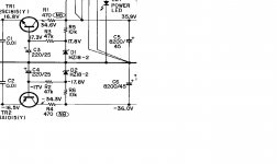
Indeed, it is...The 4.6M resistor is huge isn't it?
It's also NOT an E12 value and is wholly inappropriate in that position in your supplied (reverse-engineered?) circuit diagram (from what I can see - the image is too small).
N.B. Most Zeners need >5mA to Zener properly.
The -ve rail Zener is upside down!
Copy that circuit...The stock 250 model, and others, use the exact same circuit layout.
Adjust R1 & R4 for the appropriate voltage drop.
Good Luck!
Attachments

Hello Hamish. Thank you for the reply.
I must admit the -ve section mistake is all mine. I just sketched that half of the circuit in quickly, so people could see it exists.
Oh it's 4.7K, Yellow Violet Black Brown gap Red. I just metered the pair which is what I did before, but checked the colours for an extra layer of confirmation. It's my micky mouse volt meter. Auto Ranging on me. It does ac/dc to 20 amps. Frequency+duty. Temp. hFe. Caps+diodes. min/max. Bargraph+hold. Seems great, and gives the accuracy of a decent Fluke. It's going in the bin soon though. It moans about being on for 5 minutes, then shuts down. Even in use. Then auto ranges and makes me feel an incompetent fool. It's the first and last time that will happen. It's 'hammer time' soon.
Obviously 4.7k and 1k, I don't even need to look. That says my zener is high enough power for the circuit, if using 10k as I intend. I ordered the transistors and actually got 5 of each for £2 delivered, so that's made me happy.
Next I might be changing the 4565 op-amp in the tone section. It's all this regulator supplies now the phono stage is isolated. It's not the original and may of fried. I'm not sure what the original is though. The next stage along uses a 5532, as did the phono stage. Where it was flanked by new capacitors, but did scream loudly. So I won't pull that out, but I think a 5532 is my best option.
edit: Oh.. there is no chassis connection at all? It's a doubly insulated product. The chassis is 22vac (if my meter didn't have me again) though inductive coupling I guess. For a while I was using the case as a probe ground and most things had this 22vac difference to ground. Every single pin of the 4565 for instance. I must do something about that.
Last edited:
Well built as per the drawing, it's not right somewhere. It takes a full minute to climb to 16.4v
edit: I think maybe it's right? I'm waiting for the 220uf's to charge through 57k. The zener has 17 across it almost instantly. Must I learn about timer rates... I didn't go to bed last night.
rc calc says 63 seconds, If I'm using it right. Which the confirmation kinda says I am. A minute to hit full voltage... It seems ages. I've set my controls, seated and pulled a can ring in that time.
Last edited:
- Status
- This old topic is closed. If you want to reopen this topic, contact a moderator using the "Report Post" button.
- Home
- Amplifiers
- Solid State
- Denon 250III drawing anyone?