Paradoxically, to solve this problem you must increase the quiescent current to significantly reduce an overall stand-by current.
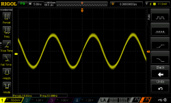
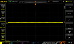
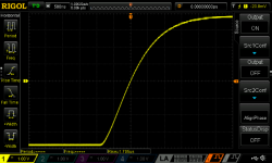
The problem is, that this board in its original, unchanged form oscillates at ridiculously high frequency. Look at the attached snapshot: almost +-100mV peak-to-peak 53MHz oscillation takes place behind the scenes, inaudible, but real and persistent. To solve this problem you should increase the quiescent current to shift the operation conditions of the devices into adequate region where crossover distortion and oscillations literally vanish. The board stabilizes and prevents oscillations caused by other events.
In the 2nd snapshot I have captured the same situation except the adjustment of the quiescent current to optimal value.
But anyways this board is prone to oscillation and other irregularities may drive it into wild oscillations and to self-destruction. The final solution to these unpredictable risks is to replace all components with reputable products.
Otherwise, this amplifier sounds great, worthwhile spending some money into more reliable components.
Attachments
Last edited:
Hi Burlusconi many thanks for the information I would be happy to replace all of the bits on the boards to get these boards reliable but I wouldn't have a clue how to increase the quiescent current. The boards when built into a box and working normally sound really good which is why I just kept buying them, in the hope I could get a reliable pair. I am now wondering if the two boards I still have working are still working because on these boards I replaced all of the power transistors.
Jolkarus - I can assure you - you don't get any warning when they are about to blow I used mine for a minimum of two weeks before they went off with a bright blue light. The longest I have had one last was approximately six weeks. I am going to try to find out how to do as Burlusconi suggests if I can find out how.
Jolkarus - I can assure you - you don't get any warning when they are about to blow I used mine for a minimum of two weeks before they went off with a bright blue light. The longest I have had one last was approximately six weeks. I am going to try to find out how to do as Burlusconi suggests if I can find out how.
Hi Burlusconi - thanks very much for this. It does account for something. When I originally hooked up the amps the sound seemed a little muddled (compared to my Icon valve amp and my previous lockdown project using TDA7293 chips). I then checked the quiescent currents - one channel was 95mA and the other only about 20mA - far too low for multiple output transistors. So I carefully adjusted R16 with parallel resistors until the current until it was in the same order. Sound seemed to improve a lot. Yes, if there was a deadband on the output the amp could easily oscillate. I have used this amp for 3 months now - sometimes at high volume and so far no problems - great sound stage and clarity. I Hope these currents are high enough. Having fixed resistors may in theory improve reliability but the quiescent is so sensitive that some careful design and integrating a trimmer would have been better. Thanks again.
Billyfish - if you adjust the quiescent with resistors in parallel with R16 - start with a very high value - 330k - or get a 1M pot and very slowly reduce. I soldered some short twisted extension wires across R16 while I was adjusting the current - then when the value was right removed the wires and soldered the right value across the resistor.
I was very careful with the power and signal routing and the star earth is just a 25mm length of thick copper wire between the amp grounds, No detectable noise or crosstalk with my ear to the speakers (MS Mezzo 6s)
Amp adjustment
Looks like I have to type this again!
Hi Berlosconi
Many thinks for this. It does explain something - when I first hooked up the amps the sound seemed a little muddled (compared to my Icon valve amp and previous lockdown project using TDA7293 chips). I checked the quiescent (whole amp) current seeing that they were set by fixed resistors. One amp was approx 95mA and the other only about 25mA - far too low for multiple output devices. I then changed the low current by a parallel resistor across R16 to about the same higher current. The sound then seemed much better - great sound stage and clarity. So far I have used the amps for 3 months - sometimes at pretty high volumes. Speakers are MS Mezzo 6. Having fixed bias resistors may in theory improve reliability but with proper design this does not have to be the case - the setting is very sensitive and critical.
Billyfish - look for the 4k7 near T10 (R16). I soldered a couple of short twisted wires across R16 and carefully changed parallel resistors until the current was in the order of 100mA. The extra resistor was then soldered across R16 and current re-checked. Start with about 330k !! I guess you could start with a 1M pot and very slowly turn it down.
I was very careful with the layout - the common ground between the amp boards is just a 25mm thick copper wire. No audible noise at crosstalk at the speakers.
PSU is 500W +/-55V switcher with extra 10,000uF across each supply.
Hi Jolkarus, many thanks for your reply would you be able to post any pictures to help me follow what you are saying since I am clearly not up to your standard. I would just like to have one pair of these boards work reliably for longer than a couple of weeks. I have built many kits but it is easy to do due to the boards telling you where each component goes.
Hi guys,
I'm glad to have shared helpful information but have forgotten to say the most important: how-to. Sorry for this omission. I was more focused to the question of the utmost importance: why. Right now I'm preparing Saturday lunch, but later on I will provide detailed instructions.
Meanwhile: enjoy the week end.")
I'm glad to have shared helpful information but have forgotten to say the most important: how-to. Sorry for this omission. I was more focused to the question of the utmost importance: why. Right now I'm preparing Saturday lunch, but later on I will provide detailed instructions.
Meanwhile: enjoy the week end.
I have just remembered that I bought a cheap pocket scope from Banggood some time ago and hauled it out. (ADS5012H). It seems to go up to 6nS sweep time. No sign of oscillation (phew!) and I also have an old RCA audio test disk that I digitised - no sign of crossover at all even at 100mV - 1V output. I have attached a photo of the general layout though it doesn't show the extra resistor as that was a bit later.
Attachments
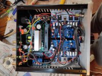
I have posted up a photo but it hasn't appeared yet - moderator I guess. I like the amp as although my Icon valve amp looks very pretty with chrome and large glowing bottles, the power is a little limited and the sound a little soft - as all valve amps seem to have. The LJMs have great reserves and attack.
But anyways this board is prone to oscillation and other irregularities may drive it into wild oscillations and to self-destruction. The final solution to these unpredictable risks is to replace all components with reputable products.
Otherwise, this amplifier sounds great, worthwhile spending some money into more reliable components.
Is there a schematic for the L20.5 somewhere?
Are you talking about major components like the transistors? Or everything including the caps, diodes and resistors. There are a number of SMD components on the board that would seem like a pain to replace.
I bought my boards directly from LJM,
Direct link to LJM's site selling the L20.5
So I hope they have the parts he says they do.
Since the board is not expensive compared to the overall cost of building the amplifier, I am willing to buy the amplifier board again, except this time as a kit and replace whatever needs to be replaced and solder it all up myself.
Bias adjustment for L20.5 amplifier
So, let's start now!
Before starting work with the PCB first read this instructions and make sure you have understood every single step. Be aware of risks of excessive bias.
There are two objectives we want to accomplish:
I. Minimize crossover distortions
II. Shift the operating conditions into the region that guarantees stability and the absence of any oscillations whatsoever
1. First look at the attached snapshot of the board. Note that the 1K resistor is replaced with 2K 25 turns potentiometer.
2. Bend the wiper lead and solder it to one of the remaining pins.
3. Adjust the trimmer to exactly 1KOhm. This is very important - do not be sloppy here: exactly one kiloOhm.
4. Solder the potentiometer to the board.
5. Fix the board on the heat sink.
6.a Use bulb protection just to verify that the amplifier works properly and then connect the rectifier directly to the mains. Adjustments with bulb protection may be erroneous because they depend on the rail voltages.
6.b Turn the amplifier on.
7. Connect the input connection to the input ground or just make sure there is no signal at the input. The presence of signal may significantly affect the bias readings!
8. Measure the voltage among the Output connector and collector of any of the output transistors.
9.a Now carefully and slowly start adjusting the potentiometer.
9.b First find the direction in which the collector voltage increases.
9.c Turn the potentiometer in increments of 1/8 of the turn, not more and then wait until the voltage drop across collector stabilizes.
I have started with original 1.2 mV and have attained the desired result with 15 mV.
How do I know that I have achieved the optimal adjustment?
10. a With oscilloscope
With the use of oscilloscope adjustment is much easier because you can see when distortion of the response to square wave ceases to exist. First stretch the rise line of the square wave to the width of almost entire screen. Initially there is a bulge, concavity which gradually fades with the increase of bias and then vanishes and turns the response into a smooth, convex line.
10.b Without oscilloscope
Without the oscilloscope you must rely on your hearing. When the amplifier sounds great just stop.
An alternative is to measure the stand-by current but this may lead to too low bias.
In my particular case I have increased voltage from 1.2 mV to 15mV across the R050 resistor.
That's all folks.
Enjoy the weekend!
Attachments
Now, the easy way
Meanwhile, I’ve spoken to Billy and he came with a good idea, he asked: can we just replace the 1K resistor with a fixed through-the hole resistor instead of meddling with that all complicated stuff?
The answer is yes: simply replace the 1K resistor with 910 Ohm resistor and that’s all. But wait before you start soldering, there’s more to that.
I have measured at 910, 953, 976 and 1000 ohm which are standard resistor values. I have measured also at 900ohm to see what happens then.
Here are the results:
900 ohm->25,94 mV
910 ohm->22,40 mV
953 ohm->17,62 mV
976 ohm->17,3 mV
1000 ohm->17,24 mV
Voltage was measured between the »OUT« connector and the collector of any of power transistors (middle pin).
Just slight crossover distortion is visible at 953 ohm (17,62mV). See the attached snapshot 1.
At 910 ohm, there is no distortion and no oscillation. Snapshot 2.
At 900 ohm (non-existent standard fixed resistor) there is no distortion too, so going lower than 910 ohm or higher than 22 mV is pointless.
However, I would suggest first to try 953 Ohms and compare the result with my measurements. Characteristics of particular devices may differ and the results may be different from mine too. Choose the resistor which results in slightly more than 22 mV.
I hope this is easier way. But be careful.
Attachments

Hi Berlusconi,
Many thanks for taking the time and trouble to help those less capable than yourself (me) with regards to carrying out your first set of instructions. I have now ordered some 953, 910 and 976 value resistors and will see what works the best. Once I have ascertained which value works best I intend to rebuild all of the broken boards and will keep them as spares. Many Many thanks Bill
Many thanks for taking the time and trouble to help those less capable than yourself (me) with regards to carrying out your first set of instructions. I have now ordered some 953, 910 and 976 value resistors and will see what works the best. Once I have ascertained which value works best I intend to rebuild all of the broken boards and will keep them as spares. Many Many thanks Bill
You're welcome dear Bill,
I must admit that I am just a beginner and just an ethusiast who wants to share modest knowledge. Perhaps my advantage is that I have a long time experience in practical, experimental applied science and I manage scientific methodology.
I'm sure you would be able to do more if you just decide so and say: yes I can. Courage.
My working skills are largely office based and at 73 I am retired and on a whim I decided to have a go so to speak and I have made some really successful kits but nothing that really needs me to have any great knowledge of electronics. Your knowledge is way above what I could now learn which is why I appreciate the help you have given me. When built into an amplifier and working these boards do sound amazing. Thank you again, Bill.
Yet, it is never too late to have fun and I guess you have lots of fun with building these midgets. There is a way you can improve reliability of your boards. Bare PCB is fine but I suspect low reliability of the on-board components in the "finished" product. Given the inherent instability and lower quality of components it is conceivable that, sooner or later, circumstances may randomly cause self-destruction of the amplifier. There are many reports that support this line of reasoning. By the way, aren't exactly you who proves this rule in the best possible way: ten times in a row. I understand 'Third time's a Charm' but ten times? It is no coincidence, it is a great deal of certainty. Such as it is, this amplifier boards are sounding great but just waiting to go in flames, or in smoke.
Therefore I have ordered a kit and populated just one board with the "original" parts from the kit. Now as I have learned glitches of this board I plan to order real components from the reputable source and re-vamp the amplifier because I plan to use it in a tri-amping LJM system: l20, L12, MX59SE.
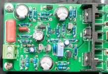
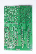
Perhaps others would like to do so. Below is a photo of the board from a DIY kit. (The photo is in high resolution, taken with quality camera. If you enlarge it you may see all details.) You may see that just surface mounting components are soldered. The rest is easy.
Therefore I have ordered a kit and populated just one board with the "original" parts from the kit. Now as I have learned glitches of this board I plan to order real components from the reputable source and re-vamp the amplifier because I plan to use it in a tri-amping LJM system: l20, L12, MX59SE.
Perhaps others would like to do so. Below is a photo of the board from a DIY kit. (The photo is in high resolution, taken with quality camera. If you enlarge it you may see all details.) You may see that just surface mounting components are soldered. The rest is easy.
Attachments
Last edited:
Hi Dave,Is there a schematic for the L20.5 somewhere?
Are you talking about major components like the transistors? Or everything including the caps, diodes and resistors. There are a number of SMD components on the board that would seem like a pain to replace.
I bought my boards directly from LJM,
Direct link to LJM's site selling the L20.5
So I hope they have the parts he says they do.
Since the board is not expensive compared to the overall cost of building the amplifier, I am willing to buy the amplifier board again, except this time as a kit and replace whatever needs to be replaced and solder it all up myself.
As a reply you may read the previous post. The SMD components are soldered on the DIY kit board, the build is straightforward, just the right components should be selected.
Regards
It is difficult to compare these two. I drove Fiat Cinquecento (midget) and Hilux (indestructible pick-up truck) and liked them both, though they belong to two quite different worlds. A60+ is quite impressive beast. Sound is different. Also A60+ has everything you need: power supply section and speaker protection. If you want the real beast, go for A60+. It sounds fantastic and can drive any speaker you want. On the other hand these LJM simple midgets let you play and learn.Hi Berlusconi, I see you are also active on A60+ clone thread. Can you compare both L20.5 and A60+ ?
- Home
- Amplifiers
- Solid State
- L20.5 AP SYS Test data My design