Those of you that are awaiting boards or have boards remember that not only is the design very, very good, Fab has written a manual second to none.
If you follow his very thorough manual you will extract every bit of performance out of the design. It is the details that count, and he tells you exactly how to handle those details.
If you follow his very thorough manual you will extract every bit of performance out of the design. It is the details that count, and he tells you exactly how to handle those details.
Ηi FabHi Niko
I would be surprised that the j112 are faked because real ones are very cheap price (0.62$) anyway.
Fab
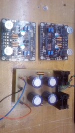
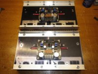
I test them with my jfet tester all gives me 4.6ma at the beginning and stabilize at 4.1-2ma
So far so good, I ajust the boards at 2.5V
Tomorrow morning thermistor and mosfets drivers installation adjusting for 3.0V.
Attachments
Last edited:
Hi meanie
55C is no problem. More than that it may be too hot for the skin when touching the heatsink...
With about 1.1A you are already in full class A at max power with 8 ohms speakers.
Only for 4 ohms speakers you benefit for more bias to stay in class A at higher power. Also at the same time, more bias means more open loop gain and slightly higher damping factor for this topology.
Fab
Thanks, Fab!
Something happened when I was trying to increase bias, my meter show the reading jumping back and forth between 65mA and 58mA.
Then I realized I had a bad quality pot (P1,P2), so I had to strip the amp again and replace the pots.
Pls use quality brands like Bourne, you will get fewer issues in the long run.
Do you simultaneously act on P1 and P2 for the bias while keeping the output offset (0V) as low as possible?Thanks, Fab!
Something happened when I was trying to increase bias, my meter show the reading jumping back and forth between 65mA and 58mA.
Then I realized I had a bad quality pot (P1,P2), so I had to strip the amp again and replace the pots.
Pls use quality brands like Bourne, you will get fewer issues in the long run.
The must be done with two multimeters because if for example you act on P1, it is normal that the value of the bias changes to P2.
Do you simultaneously act on P1 and P2 for the bias while keeping the output offset (0V) as low as possible?
The must be done with two multimeters because if for example you act on P1, it is normal that the value of the bias changes to P2.
Thanks for your advice
Yes, I did.
I use 3 meters, monitoring the output while adjusting both P1 and P2 simultaneously. Yet the figure jumps over the place.
The other channel responded to the adjustments well.
Thanks, Fab!
Something happened when I was trying to increase bias, my meter show the reading jumping back and forth between 65mA and 58mA.
Then I realized I had a bad quality pot (P1,P2), so I had to strip the amp again and replace the pots.
Pls use quality brands like Bourne, you will get fewer issues in the long run.
Hi Meanie
i have the same issue.... cold welding bad join on trimmer Vishay ...solved..
T93YA102KT20 Vishay / Sfernice | Mouser Greece
my measurements were slowly coming to me...
Last edited:
Hi Meanie
i have the same issue.... cold welding bad join ...solved..
my measurements were slowly coming to me...
I will recheck while changing the pots.
It was working fine @1.3A till this attempt to increase bias...
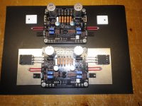
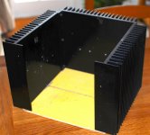
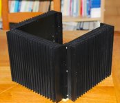
Will be taking a similar route! I already have x2 of these Krell Clone chassis! Was thinking of using two heatsinks with a 5mm top, bottom and rear panel and 11mm front panel. These should make x3 stereo amps
The individual sinks are 228mm x 250mm net of flanges and are 40mm fins + baseplate & top from 8mm plate). I would also use a 10mm heat spreader.
Is this enough cooling for one board per heatsink? I am reposting a pic as it now stands with x3 such heatsinks.
Thanks.
On re-reading the above quote I found a couple of measurement typos! I have corrected them in red in the quote above. As it was well outside the 30min editing opportunity I think that this is the best way to correct the post and also to get some response.
Many thanks
")
Attachments
Last edited:
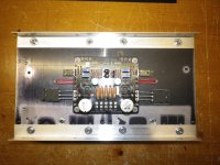
The individual sinks are 228mm x 250mm net of flanges and are 40mm fins + baseplate & top from 8mm plate).
brianco,
Looks like you have enough heat sink there. The area you have with 228mm x 250mm heat sink is larger than the 300mm x 165mm heat sink of the 4U Deluxe chassis available at the diyA store.
The fins also have nice little corrugations, helping increase the fin surface area and heat dissipation.
Last edited:
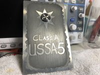
After several attempts etching, I have a front badge for the USSA5, Yahoo!!
Mmmm i like it Vunce .. looks vintage ...
If one day your USSA gives up, this badge can be used as a tombstone!After several attempts etching, I have a front badge for the USSA5, Yahoo!!
- Home
- Amplifiers
- Solid State
- USSA-5 Build with Review