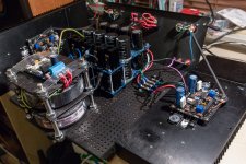
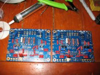
Finally finished the amp, mainly because of lack of time and the fact I had to expand a previous 4U/300 build to a 4U/400 chassis so I could stack the PSU caps and reduce wiring. I build the system dual mono with 2x300VA toroidy trafo's, diyaudio store PSU boards with 44000uF>0.12R>20000uF/rail delivering 2x23Vdc. For C5/C6 I used Nichicon UKA 3300uF, I think about swapping them for the EGPD's from the BOM. The bias on the front amp is 30mA, the main bias is 1.2A.
I listened to the amp; fantastic! I build 5 other class A ones and I checked them with my A/B switch. The USSA5 is more detailed, better soundstage and dynamic than my builds of the Pass M2 and Tubelab TSE. The difference is very small but noticeable if you pay attention.
Next I listened to it A/B side by side to the Pass VFET2 (original TeaBag boards) and again while the difference was even smaller, it is still slightly noticeable, the USSA5 presented a little better detail and nicer cleaner voices, soundstage was even.
I measured both the VFET2 and the USSA5 with my EMU soundcard and ARTA. The USSA5 measured very clean (THD, H2, H3, FreqResponse, Noise floor) compared to the other amps, not that I value measurements above listening, but nice to check.
Damping factor I measured around 8...10
I am very happy with my build, It's worth finishing the amp! thanks Fab
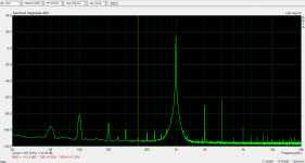
Attached are two pictures of the amp nearly finished and an ARTA -12dBV measurement
I listened to the amp; fantastic! I build 5 other class A ones and I checked them with my A/B switch. The USSA5 is more detailed, better soundstage and dynamic than my builds of the Pass M2 and Tubelab TSE. The difference is very small but noticeable if you pay attention.
Next I listened to it A/B side by side to the Pass VFET2 (original TeaBag boards) and again while the difference was even smaller, it is still slightly noticeable, the USSA5 presented a little better detail and nicer cleaner voices, soundstage was even.
I measured both the VFET2 and the USSA5 with my EMU soundcard and ARTA. The USSA5 measured very clean (THD, H2, H3, FreqResponse, Noise floor) compared to the other amps, not that I value measurements above listening, but nice to check.
Damping factor I measured around 8...10
I am very happy with my build, It's worth finishing the amp! thanks Fab
Attached are two pictures of the amp nearly finished and an ARTA -12dBV measurement
Attachments
Attached are two pictures of the amp nearly finished and an ARTA -12dBV measurement
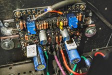
Can you make a close-up picture from your stuffed PC board and upload it, soon I start stuffing my PC boards that would be a great help.
I am willing to provide an e-mail address and send it to me in case that too much to upload on the thread.
Thank you
Greetings
from mannual rev 0.4.5 "´8.14 Front End amplifier testing
· Connect V+ and V- and PGND (the one close to V-) to power supply (from 15Vdc to 30Vdc).
· Adjust P1 for about 0,3Vdc between TP6 and V-.
· Adjust P2 for about 0,3Vdc between TP5 and V+."
Are P1 and P2 correct? I can change voltage on TP6 only with P2 and P1 with TP5. Minimun voltage I can get is 0,6V.
Yes P1 and P2 are correct and for the settings on the black PCB you have to connect to GND (PGND near V- was on the red and blue versions).
Did you put the good values of the trimmers P1 and P2 (10K) because it happened to me the first time to be wrong with the P3 and P4 (1K)?
Did you put the good values of the trimmers P1 and P2 (10K) because it happened to me the first time to be wrong with the P3 and P4 (1K)?
Hi asandenFinally finished the amp, mainly because of lack of time and the fact I had to expand a previous 4U/300 build to a 4U/400 chassis so I could stack the PSU caps and reduce wiring. I build the system dual mono with 2x300VA toroidy trafo's, diyaudio store PSU boards with 44000uF>0.12R>20000uF/rail delivering 2x23Vdc. For C5/C6 I used Nichicon UKA 3300uF, I think about swapping them for the EGPD's from the BOM. The bias on the front amp is 30mA, the main bias is 1.2A.
I listened to the amp; fantastic! I build 5 other class A ones and I checked them with my A/B switch. The USSA5 is more detailed, better soundstage and dynamic than my builds of the Pass M2 and Tubelab TSE. The difference is very small but noticeable if you pay attention.
Next I listened to it A/B side by side to the Pass VFET2 (original TeaBag boards) and again while the difference was even smaller, it is still slightly noticeable, the USSA5 presented a little better detail and nicer cleaner voices, soundstage was even.
I measured both the VFET2 and the USSA5 with my EMU soundcard and ARTA. The USSA5 measured very clean (THD, H2, H3, FreqResponse, Noise floor) compared to the other amps, not that I value measurements above listening, but nice to check.
Damping factor I measured around 8...10
I am very happy with my build, It's worth finishing the amp! thanks Fab
Attached are two pictures of the amp nearly finished and an ARTA -12dBV measurement
Thanks for the compared review. This is informative.
")
Just a few comments for your consideration:
1) your measured damping factor value is way too low. It should be between about 30 to 45. You need milivolt Meter precision and a precise resistor load value otherwise the calculation can give misleading results. Also, you must ensure that it is taken at power where the PSU does not sag.
2) your THD measurement appears to be done at high power level. Can you check the THD at same levels as I have done. Refer to post 67 for 1Wrms where second harmonic is clearly higher than 3rd:
USSA-5 Build with Review
Also for 6w and 10wrms at post 73:
https://www.diyaudio.com/forums/solid-state/323778-ussa-5-build-review-8.html#post5469753
THD is not that important but it is worth checking.
3) your heatsink seems big enough for more than 1.2A bias. If you have 4 ohms speakers you could get higher power in class A mode.
Fab
Last edited:
Asanden,
Thanks for your subjective review.
As to your objective analysis I also have questions like Fab.
When you state -12dBv, that is 0.25V RMS which if using an 8 ohm resistor load is 7.8 milliwatts. That doesn’t make much sense.
Your graph states ~ +15dBV which is 5.88 V RMS which if using an 8 ohm resistor load is 4.3 watts. The spectra of the graph however appears highly unusual with very large distortion components for such low power.
Can you double check?
2.83V RMS for an 8 ohm load is 1 watt and is the equivalent to 9 dBV.
Thanks,
Anand.
Thanks for the responses
I used 7.5 ohm load (15//15)
The graph I supplied was -12dB in, 15.4db out according to Arta; so the amplification is fairly high 27.4dB vs 20dB, I will remeasure/check the in output levels with my multimeter, and recheck the Arta calibration.
Regarding the damping factor, I measured it fairly high loaded: about 12W
I applied ca -8dB (0.871V) to the input.
I have a fairly good multimeter and I checked the MM measurements with Arta Scope; 9.291Vrms no load, 9.475Vrms with load
I will redo the measurement with different output levels and on both chanels.
Regarding the THD:
I don't mean to state or discuss THD numbers, it is more a way of checking the build is within expectations.
I have a EMU 0202; no profesional equipment, I use it more for relative measurments (between amp's) than absolute measurments.
Post #67 has H2 at -95dB and H3 at -103dB (1W/8R)
Post #74 has H2 at -92dB and H3 at -90dB (6W/8R)
Post #74 has H2 at -88dB and H3 at -83dB (10W/8R)
very nice, mmmm.... my measurents done at 12W, 8W, 6W, 3.3W, 2.1W, 1.2W are 10..20 db off, I shall re-calibrate and re-measure.
Btw, The amp sounds great, I have all the trust in fab's measurements and design.
I use 4..5 ohm speakers, I might increase bias
There was a request to post a picture of the PCB, I believe there a better ones posted already.
Attachments
asanden what brand your 3300uF Audio capacitor?
They look like Nichicon KA.
https://www.mouser.ca/datasheet/2/293/e-uka-884128.pdf
Hi asanden
Thanks again for your feedback
For that damping factor measurement I meant that the precision on your 7.5x?ohms exact value makes a big difference in the calculation. Also have in mind that if the resistor is heating then its value will increase and affect the result. Ensure to test at power low enough with a high power resistor to increase the precision.
As for my FFT results, you need to add +10dB to the numbers you have indicated since at 1K Hz I have -10dB level. The goal is to ensure to not saturate your input measurement circuit with a too high level otherwise you measure THD created by your sound card.
Keep us posted if you increase the bias.
Fab
Last edited:
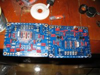
Yesterday I started (stuffing) this project.
I installed all the 1/2 W resistors, J Fets, 5W resistors, Zobel network (maybe I will have to remove this?).
I am confused with Q1,Q2 & Q3,Q4, I read at the instruction to match Q1 to Q2 and Q3 to Q4.
After I read to use the Higher hfE for Q1 and Q3 positions.
If I match the mentioned 2 transistors how to pick the the higher hfE?? Should be (100%) matched or not?
Can someone explain this to me please.
I do not want to stuff those transistors until I do not understand that. I use silver solder and second time does not want to melt, If I have to remove some parts that can destroy the PC boards, rather wait or ask than solder and later remove it.
Does the Zobel will interfere with the measurements I mast done later?
Please let me know
One more thing- can I use 5K trimmer instead of 10K.
I only have 2PC 10K at home, I ordered from eBay but will take 30-40 until arrives.
Thank you
I installed all the 1/2 W resistors, J Fets, 5W resistors, Zobel network (maybe I will have to remove this?
).I am confused with Q1,Q2 & Q3,Q4, I read at the instruction to match Q1 to Q2 and Q3 to Q4.
After I read to use the Higher hfE for Q1 and Q3 positions.
If I match the mentioned 2 transistors how to pick the the higher hfE?? Should be (100%) matched or not?
Can someone explain this to me please.
I do not want to stuff those transistors until I do not understand that. I use silver solder and second time does not want to melt, If I have to remove some parts that can destroy the PC boards, rather wait or ask than solder and later remove it.
Does the Zobel will interfere with the measurements I mast done later?
Please let me know
One more thing- can I use 5K trimmer instead of 10K.
I only have 2PC 10K at home, I ordered from eBay but will take 30-40 until arrives.
Thank you
Attachments
Will check if I've some 10K trimmers for you .
Thanks for that.
I think I can wait to receive the one I just purchased from eBay. Last week I purchased also the 0.05R 5W resistors. I forget when I ordered my items from Digi-Key.
Until those arrives I thought I can set up the one side I have all the trimmers.
To have some experience.
I don't know why I have this funny felling with (only) this project it is hard to get it done, I built more than 100 amps (OK some project were never 100% finished others where built 3 times or even more) but I never felt this way.
Because of that I want to get all help and advise one can get.
You can see on the new image at one PC board after the small BJT I ca start the measurements. Just need to know how well those BJT's has to be match. I can do 100%, I have a many BC550C & BC560C.
Attachments
I am confused with Q1,Q2 & Q3,Q4, I read at the instruction to match Q1 to Q2 and Q3 to Q4.
After I read to use the Higher hfE for Q1 and Q3 positions.
If I match the mentioned 2 transistors how to pick the the higher hfE?? Should be (100%) matched or not?
Thank you
Gaborbela,
I think the notes mean that in the case where one has only a few BJT's, then the higher hfe ones should go in the Q1 and Q2 positions. The tolerances in the notes are quite broad and should be easy to meet.
Although I'm sure someone with more knowledge will step in here shortly, if you can do a 100% match and have patience for testing all those transistors, I think that it will be fine.
As a side note, I have observed that 550c/560c require little effort to get adequately matched pairs. Go for it dude.
Hi Gaborbela
Extract of manual:
“8.5.2.1 Measure HFE of transistors (optional)
Place higher HFE transistors in Q1 and Q2 position;
Match Q1 with Q2 (<= 30%)
Match Q3 with Q4 (<=50%)”
I think it is clear. Matching is not that critical anyway but if you can do it go for it.
The manual is done in steps that you must pass by testing so you almost cannot fail at the end of assembly.
Yes there is a few things to calculate, measure and test but the extra work make it more a diy experience and you may learn a few things in the process, I hope...
Keep it cool and everything will go well
Good luck
Fab
Last edited:
Hi Fab,
So, my heatsinks turned up and I've proceeded with the USSA-5 assembly. At the moment I am up to the testing of the Front End where I must set 0.3VDC between test points using a couple of potentiometers. The first amp worked as you would expect with 0.3VDC found quickly and it being stable in both channels.
However, the second amp has an issue where the 0.3VDC does not stay stable. I set it using the first pot, then set it in the second pot and go back to check the first and it the voltage has moved. So I reset it to 0.3VDC and check the second pot and now it has moved...and round and round I go ultimately getting nowhere.
I've looked at the components and both boards have the caps and diodes in the same orientation and the driver transistors are in their correct positions.
I'm not sure what to check next. My guess is that one of Q1, Q2, Q3, Q4 needs replacing...but that is only a guess.
Cheers,
Anthony
- Home
- Amplifiers
- Solid State
- USSA-5 Build with Review