Enjoying music in mine! Hehe
Delightful !
Ciao!
Do
Do,
Me too!
Cheers,
Greg
Hello All:
I am up to section 8.17.1 , Adjust output MOSFET current close to intended final bias.
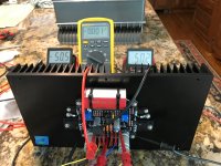
Everything has measured fine up to this step. When I apply power, TP4/V- and TP2/V+ read 0.00 volts, and the offset at output is about 0.5 volts. The MOSFETS are not getting warm. I get the same readings on both boards, so I believe parts are installed correctly.
Should I proceed to increase/decrease P1/P2 to turn on MOSFETS?
Steve
I am up to section 8.17.1 , Adjust output MOSFET current close to intended final bias.
Everything has measured fine up to this step. When I apply power, TP4/V- and TP2/V+ read 0.00 volts, and the offset at output is about 0.5 volts. The MOSFETS are not getting warm. I get the same readings on both boards, so I believe parts are installed correctly.
Should I proceed to increase/decrease P1/P2 to turn on MOSFETS?
Steve
Hi
If all previous steps measured fine then it is normal to get 0 volts before adjustments if the vgs off of the mosfet are on the high side (red color band for example). Therefore you can proceed to adjust P1/P2 to get output bias while keeping DC offset close to 0 (<50mv until final bias). At final bias you can tweak dc offset to < 5mv once température is stabilized.
Fab
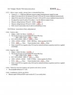
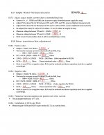
You got 100% for your testApparently forms behave differently on iPhone and iMac version of Acrobat. Here are jpg images of my results.
")

Fab
HiThanks Fab. Will post VGS calcs for confirmation soon.
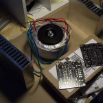
You have clean assembly, proper positioning and good size heatsink. Your input cap is a little (far) more expensive than the one specified in the BOM...
Fab
Thanks Fab. Yes it is a fat cap, but I selected it because I have a similar one in an amp and it sounds quite good. I have now started a build thread on my USSA-5 amplifier: My USSA-5 Build ... Switched at Birth
Steve
Steve
BTW, my lateral mosfets from Profusion do not have any color code on them
Then you haven't ordered the -S version.
My ussa-5 and USSA-3 amps use Alfet mosfet without selected grades. Same for other builders too.yup I missed the -S seriesI wouldn't expect more from myself
I think we will see how it goes.
Fab
My USSA-5 has allfets without special grade and it's the best!yup I missed the -S series
I think we will see how it goes.
I planned to make a USSA-3 and I bought EXICON without grade (color) and I have no problem because I'm not sure that a difference in listening can be heard.
In short, your mosfets are perfect.
I don't use any of those better matched version and the amp is incredible! Fear not my friend!
My ussa-5 and USSA-3 amps use Alfet mosfet without selected grades. Same for other builders too.
Fab
My USSA-5 has allfets without special grade and it's the best!
I planned to make a USSA-3 and I bought EXICON without grade (color) and I have no problem because I'm not sure that a difference in listening can be heard.
In short, your mosfets are perfect.
ok cool then , I was almost sure that I heard Fab saying that they don't need to be matched but didn't want to mislead anyone in case I was wrong
Thanks guys, it is 9PM Saturday here and I still have hope to start putting it together this weekend
Are you saying 2x 300mmx140mmx40mm ? So, around a 4U diyaudio store power amp chassis? I have a smaller chassis I was considering using a copper plate running across the interior of each heatsink to perhaps get the amp running cooler in a smaller footprint.To give you an idea my USSA-5 with 25Wrms full class A (into 8 ohms) has about 300mm x 140mm x 40mm heatsinks (standard vertical fins) for about a little less than 50C (20C ambient).
Smaller heatsink will allow less bias thus less power in class A for the same temperature.
Fab
Anyone attempt this kind of thing and can point me in a direction for photos or build info?
- Home
- Amplifiers
- Solid State
- USSA-5 Build with Review