Hi Amadeus00, I also had some trouble with the adjustments by following the step-by-step instructions in the manual. In the end, it was all "just" an question of blindly and exactly following instructions vs. understanding how things work. I am more in the "understanding" camp... so I came up with my own recipe for adjustment (which I prefer, of course...). See here.
HiHi FAB,
Thanks for reply. After I posted my issue yesterday, I decided to continue. I connected two VU meters to TP6 and V- and TP5 and V+ at the same time. By adjusting P1 and P2, I was able to get 300mV on both measured points. However, I needed to find balance because increasing/ decreasing of voltage was not linear or same for P1 and P2. Was also able to get 50 mV between TP4 and V- and TP2 and V+. After that, I measured OFFSET on output and it was 90mV, so I adjusted it to 0, however after 15 minutes it was 2,7mV and growing continuously (heatsinks were quite warm as well). There is one question: should I wait until heatsink reach stable temperature and then adjust offset or just adjust it immediately? Then I checked voltage between TP4 and V- and TP2 and V again, was same for both measured points at level of 48,7mV. VGSN was 0,914V and VGSP 1,509V. Back to your initial question, I was able to reach point 8.17. I checked diodes (types and polarity-should be OK). Just writing what I did in order to get approval or maybe some guidance. After you can confirm my results, I can do the math for Rv1a and Rv2a and then try to do another adjustment. Nevertheless, I will continue tomorrow since I am at work whole day today.
PS: You can see my PCB installation on heatsink. Not sure if this disproportionality of transistors layout might affect thermal characteristics and have some impact on overall results. I was considering also transformer and PSU position in my chassis, which is why I decided to install it that way.
One more thing. I was using my original PSU for all adjustment steps, only for 8.17 as intended in your manual. Not sure if it is good or bad …
Amplifier heatsink - based on your selection from the picture - is expected to be close to 50C which is perfect. The DC offset final adjustment must be done after heatsink temperature stabilized as for most power amplifiers. It is normal that upon power-up of the cold amplifier DC offset be higher but eventually reaches the value adjusted while it becomes warm.
You can use any suitable PSU you want for the testing.
Your measures are perfect and as per the manual.
You seem on the good path, please continue.
Fab
Thank you mbrennwa for your reply. I know what you mean.
I was doing some calculations. I measured VGSN and VGSP yesterday again. After 40 minutes of running one channel VGSN was 0,909V and VGSP 1,502V (which is almost the same as the last time). Based on that, RV1A should be 22,40 ohms. When dealing with the negative side, value for RV2 was -7,47. I changed calculations from 47 ohms for R14 to 30 ohms. In that case RV2A should be 11,94083 ohms. Could someone confirm my calculations? However I got some points. I do not understand the equation of RV2=RV2A//RV2B, at least its formal mathematical description ... double brackets // should represent an integer division ... instead of that I was calculating 1/RV2A=1/RV2- 1/RV2B.
I was doing some calculations. I measured VGSN and VGSP yesterday again. After 40 minutes of running one channel VGSN was 0,909V and VGSP 1,502V (which is almost the same as the last time). Based on that, RV1A should be 22,40 ohms. When dealing with the negative side, value for RV2 was -7,47. I changed calculations from 47 ohms for R14 to 30 ohms. In that case RV2A should be 11,94083 ohms. Could someone confirm my calculations? However I got some points. I do not understand the equation of RV2=RV2A//RV2B, at least its formal mathematical description ... double brackets // should represent an integer division ... instead of that I was calculating 1/RV2A=1/RV2- 1/RV2B.
Hi Amadeus
I believe you got the understanding right")
1) 1.502V / 0.022A =68 ohms. 68= R13 + RV1
RV1 = 68 - R13 = 68 -47 = 21 ohms (you can use 22 ohms)
// —> parallel equation
RV1 = RV1A in parallel with RV1B. You can use only RV1A of 22 ohms (RV1B not installed) or a parallel combination of RV1A and RV1B giving 22 ohms.
2) 0.909V / 0.022A = 37 ohms. 37 = R14 + RV2
Just replace R14 for 36 ohms and use wire jumper for RV2A or RV2B.
Note that your final output bias current should be higher than 1A so the final VGSP and VGSN will be higher thus the driver current (23ma) will increase (for both negative and positive sides) and that is the goal also.
Therefore, you are still on the good path
Fab
I believe you got the understanding right
1) 1.502V / 0.022A =68 ohms. 68= R13 + RV1
RV1 = 68 - R13 = 68 -47 = 21 ohms (you can use 22 ohms)
// —> parallel equation
RV1 = RV1A in parallel with RV1B. You can use only RV1A of 22 ohms (RV1B not installed) or a parallel combination of RV1A and RV1B giving 22 ohms.
2) 0.909V / 0.022A = 37 ohms. 37 = R14 + RV2
Just replace R14 for 36 ohms and use wire jumper for RV2A or RV2B.
Note that your final output bias current should be higher than 1A so the final VGSP and VGSN will be higher thus the driver current (23ma) will increase (for both negative and positive sides) and that is the goal also.
Therefore, you are still on the good path
Fab
Last edited:
Thanks for a quick reply FAB. I do not have currently 18ohm resistor so I will have to stick with a parallel combination of RV1A and RV1B giving 18 ohms (RV1A=22,4ohms). In second case, again I do not have 39ohm resistor, but what I can do right now is to change R14 to 30ohm, RV2B to 25ohms, and then RV2A to 15 ohms and it should work. RM4 is 39,5ohms- R14 (30ohms) is 9,52173 which is parallel RV2A(15,3ohm) and RV2B (25ohm). What do you think about it? When making offers from mouser I bought bunch of different values of vishay/dale resistors, so I want use what I got right now.
When making offers from mouser I bought bunch of different values of vishay/dale resistors, so I want use what I got right now.Thanks again FAB. Will post you on my update tomorrow. Anyway one more question. Do you think is it a good idea to use soft start power module based on solid state relay? For example SSC – 25 Soft Start Controller? I know it is not standard approach and there might be more noise generated. That is why I am asking. I will use 2 toroid transformers from TOROIDY 300VA each.
You are welcome.
Regarding the SSR soft start the only advantage I can imagine over power relay contacts is that the latter may degrade over time.
SSR can offer advantage over relay contacts for speaker DC protection against amplifier fault because SSR can handle much higher fault current.
Fab
Regarding the SSR soft start the only advantage I can imagine over power relay contacts is that the latter may degrade over time.
SSR can offer advantage over relay contacts for speaker DC protection against amplifier fault because SSR can handle much higher fault current.
Fab
I'm confused now: I wanted to get this one at mouser: J112 InterFET | Mouser Deutschland - now I find this one at Reichelt: Security Check - the price difference is quite big, do I mix sth. up here? Thank you!
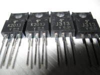
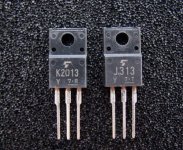
M3, M4 Mosfet Pair
Do these appear to be authentic?
1 Pair | 2SK2013 + 2SJ313 | New Original TOSHIBA | eBay
Do these appear to be authentic?
1 Pair | 2SK2013 + 2SJ313 | New Original TOSHIBA | eBay
NicMac should have still some for sale. Try to send him a PM.
https://www.diyaudio.com/forums/members/nicmac.html
https://www.diyaudio.com/forums/members/nicmac.html

NicMac should have still some for sale. Try to send him a PM.
https://www.diyaudio.com/forums/members/nicmac.html
- Home
- Amplifiers
- Solid State
- USSA-5 Build with Review