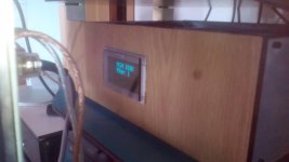
I did some dry fitting of the USSA-5 PCBs, SLBs, transformer, and other bits and pieces to see if and how everything will fit in my Aleph chassis. I guess I have one less excuse to get the build started...
Attachments
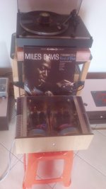
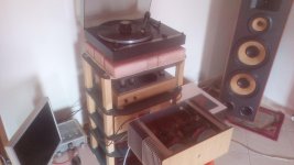
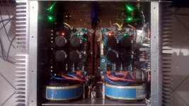
It plays music from early morning..... mmmmm what can i say for this amp....... Amazing sound with the dac from my best friend Sonny Mirand Audio.All details is here bass extended harmony in all frequencies , my speakers are 92-93 db 300,W 4Ω yes i have a lot of volume. Ι like it..... Ambient temp 21-22 outside heatsinks 44 C bios 1.25-1.3A varies.... I am playing without protection.... I trust this amp and his measurements.. A lot of thanks Fab, Project16 for your amp- parts.
Attachments
Last edited:
It plays music from early morning..... mmmmm what can i say for this amp....... Amazing sound with the dac from my best friend Sonny Mirand Audio.All details is here bass extended harmony in all frequencies , my speakers are 92-93 db 300,W 4Ω yes i have a lot of volume. Ι like it..... Ambient temp 21-22 outside heatsinks 44 C bios 1.25-1.3A varies.... I am playing without protection.... I trust this amp and his measurements.. A lot of thanks Fab, Project16 for your amp- parts.
Hi Niko, you are welcome and glad that you like what you hear. You have a nice built and sure have a very good power supply as you have an imaginative way of implementing it with the ripple heater
")
I too love the sound of AKM DAC in combination with USSPA2 preamp and USSA5.1 amp in my setup.
I like your description of the bass reproduction as it is also the way I feel it when I hear the bass cords vibrating...
Thanks again for posting.
Fab
Last edited:
Had another 'bad health' month but again recovering. Have practiced soldering but hand tremble too bad for tight PCB work. However a local electronics company has agreed to stuff and solder if I supply parts. I hope that here is no objection to me going down this route.
Brianco i wish you all the best for your health..
Im available also to assemble your parts if you wish..
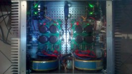
Now im playing with protection board from Project16.
Im available also to assemble your parts if you wish..
Now im playing with protection board from Project16.
Attachments
Last edited:
Grounding question: "GP" vs "GC"
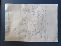
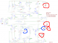
I have a question regarding the grounding with the USSA PCB. The schematic shows two "ground points" for the PCB: "GP" and "GC", but they appear to be the same GND. More specifically:
I guess there's something in the manual that was not clear to me, but I don't understand what / where this is.
I attached a (blurred) copy of the schematic from the manual, with marks to illustrate my questions.
I have a question regarding the grounding with the USSA PCB. The schematic shows two "ground points" for the PCB: "GP" and "GC", but they appear to be the same GND. More specifically:
- What do the "GP" and "GC" abbreviations refer to? GP = "ground power" or "ground plane"? GC = ???
- GP and GC are both shown to connect to common GND in the schematic. In addition to this, GP and GC are also connected to each other via a 1 Ohm resistor (R27). Since GP and GC both connect to common GND, both sides of the resistor are effectively connected to common GND. The resistor does not seem to do anything! What's up with this?
- The manual says that GP and GC should have independent connections to the PSU ground. Why is that? They are already connected to the same GND (see above), so I don't see why they need separate wires to the PSU ground.
I guess there's something in the manual that was not clear to me, but I don't understand what / where this is.
I attached a (blurred) copy of the schematic from the manual, with marks to illustrate my questions.
Attachments
Grounding
Hi Mbrennwa
see section 12.6 of the manual for ground return connection. I have added R27 for better understanding.
GC is the input/feedback ground. GC goes to 1 ohms resistor and then goes to GND tab on pcb.
GP is the power ground (psu cap on the board). GP goes to PGND on the pcb.
Both GND and PGND tabs go to PSU ground as does speaker return. The PSU ground is the main star connection.
Therefore GC and GP are not at same potential ( 1 ohms resistor as R27). The schematics shows the complete system (ussa5 pcb+ psu + speaker load).
This is 2 connections scheme to PSU compared to a single one. Both schemes have advantages and disadvantages. Bonsaï had made the comparison in one thread somewhere in the forum. I selected the 2 connections schemes And peoples reports no noise issue in their builds. You could also short GND and PGND on the pcb and then connect a big single wire to PSU ground if you want to compare. In the FSSA amp pcb I have provided and additional tab to easily try both ground return schemes.
Fab
Attachments
Last edited:
The schematics shows the complete system (ussa5 pcb+ psu + speaker load).
Ahaaa! I thought the schematic shows the PCB only. To avoid this confusion, you could show the PSU as a separate unit on the schematic, with the ground wires going from the amplifier PCB to the PSU star ground.
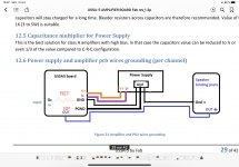
see section 12.6 of the manual for ground return connection. I have added R27 for better understanding.
I had looked at 12.6 before, but that confused me even more because GP is missing in this drawing. Combining the schematic and the 12.6 drawing, there is GC, GP, GND, PGND and the "ground" symbol in the schematic. That's 5 different grounds, which caused my brain to run in circles.
GC is the input/feedback ground. GC goes to 1 ohms resistor and then goes to GND tab on pcb.
GP is the power ground (psu cap on the board). GP goes to PGND on the pcb.
Both GND and PGND tabs go to PSU ground as does speaker return.
Ok, wait a minute...
1. GP = PGND on the PCB
2. GP = PGND has a dedicated connection to the PSU ground
3. GC has a direct connection to the to the PSU ground (according to the schematic)
==> Questions:
A. What is the purpose of the 1 Ohm resistor between GP and GC, which are both grounded?
B. Which "ground" does the "GND" label refer to on the PCB in drawing 12.6?
GND = GP? GND = GC?
I am not sure, but I would guess that GND = GC, since GP = PGND already has a connection to the PSU ground.
I believe it would be useful to clean up the various ground labels/names used for the (same?) ground(s) throughout the manual. For example, "GP" is missing in 12.6. On the other hand, "PGND" and "GND" are not used in the schematic. I am very confused by this. I believe you could just ditch the "GC" and "GP" everywhere and just use "GND" and "PGND", which would clear the smoke for me (and maybe others as well).
Thanks for your continued support with the USSA!
Hi Mbrennwa
GC does not have a direct connection to PSU ground.
A. This is an “isolation” resistor to prevent power ground current to contaminate the low power (input, feedback, ground plane ) ground current. Remember that current follows the lower impedance path. This is standard procedure in most amplifiers. You can check Doug Self amplifiers book for further details.
B. Yes
The schematics comes from my simulator application and I an using my own standard for labeling of grounds. The schematics is only provided for understanding but not required to assemble the amplifier since all steps are provided in the manual and all referencing to the pcb marking. I may simply add GC= GND and GP= PGND in the next manual iteration. Have in mind that this manual is the result of reviews by many members since built over 30 times (that I am aware) and pcb sold to hundred of different members.
Thanks for your appreciation.
How are you progressing on your build?
Fab
Last edited:
GC does not have a direct connection to PSU ground.
...
B. Yes
...
I may simply add GC= GND and GP= PGND
Well, according to the schematic GC connects to GND, which in turn connects to the PSU ground according to 12.6. This means that GC does directly connect to PSU ground. Do you see why I am confused?
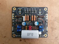
How are you progressing on your build?
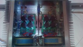
See photo: boards are almost completed, current adjustments are done using (use a lab bench PSU). The next step is to set up the MOSFETs and thermistor on a dummy heatsink and do a first test of the complete amp. Then I need to work on the chassis and final PSU, install the amp in the final chassis, and tweak the current and voltage adjustments.
Attachments
Sorry for insisting... I checked the connections on the board. The only connection of GC to GND is through R27. This means that your annotation in post 1475 is correct. However, the GC connections to GND as shown in the schematic at C1, C3 and C4 are not correct. I'd suggest to correct this in the next revision of the manual.
- Home
- Amplifiers
- Solid State
- USSA-5 Build with Review