Will do more tonight or tomorrow morning.
As far of capacitors all being new stock from digikey brand new nichicon, and muse for electrolytic and film caps for small values 0,01uF and picofarads are silver mica's.
Current miroir will go further tests.
But how about Q13 MPSU10 low hfe value??
Thanks
As far of capacitors all being new stock from digikey brand new nichicon, and muse for electrolytic and film caps for small values 0,01uF and picofarads are silver mica's.
Current miroir will go further tests.
But how about Q13 MPSU10 low hfe value??
Thanks
HK Citation 16A DC offset
Interesting replacement of zener CR5 a 5,1v did make a changed by having now 0,15v dc now
CR6 was also replaced with the same zener batch from digikey.
Now my voltage checks;
1/ Check the DC voltage at the junction R1 and R2. Lets be sure that no stray DC voltage is appearing at the input causing a 'valid' offset condition. Compare the voltage with the good channel.
R1 -0,184v, both Q1 bases are at -0,21 v
Q1 emitter at -8,78V and collectors ar +8,20v.
2/ The caps around the feedback network, C4 and C5 could imbalance the DC conditions if one were short or leaky. The AC performance would still be OK. That's definitely one to check.
All caps are new Nichicon and Muse from Digikey.
3/ C3 is needed for stability but I'm not 100% sure what the effect would be if leaky.
Same as above
4/ Check the voltage across R5 (560 ohm) is around 650 millivolts give or take. Compare with the good channel.
R5 -9,85 one side and the other -0,927v
5/ Compare the voltages across the current mirror resistors, that's R6 and R7, R8 and R9, R24 and R25. Each pair should be similar. Compare to the good channel.
All mirror volts are good to compare with the good channel.
R6-7-8-9 are at +9,45v
R24-25: are at -9,27V
Will check further tonigh, thanks
Interesting
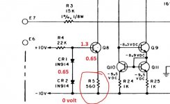
Item #4, voltage across 560 ohm. Something is amiss with that one. The transistor is run as a constant current sink with the base voltage clamped by the two diodes.
That's worth rechecking. With the black lead of your meter on the -10v rail (which I have now marked 0) you should read the following voltages.
Attachments
0.6v is fine. I read your previous figures as -9.85 and -0.927 (9.27 ?) hence the previous train of thought. More thinking
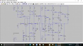
I've thrown the front end of the circuit into a simulation and (surprisingly) find that changes to the Zener voltages have only a little effect. That is both the 5.1v zeners and the 10 volt ones. The untrimmed offset voltage is 46mv and the preset swings that to -100mv with the wiper at +10 volts and +200mv with the wiper at -10v.
Have any other parts been changed ? Unless I've missed it somewhere, what is the history of the amp ? Even something like spillage and a slightly conductive residue on the PCB could do something like this, particularly around Q1 and associated components. We have to cover all possibilities.
Attachments
Hello,
I've tried a couple of things. yes it is -9,27v. PCB are very clean under and over the parts side. Cleaned with ISO 99% alcohol .
CR1-2 do measures 1,2v ok with the other channel.
R4 voltage drop measures 17,45 on the good channel and 18,6v on the problematic one.
Did replaced R4 with 10Koms with a series diode 1N914 , no results on changing the offset go to smaller than -150mV. (negative).
R5 is 560 ohms and voltage across is 0,6v.
Voltage on R1 is -0,184v from ground C.T.
Replaced Q8 with 2N3904 hfe: 120 measured before install. Did not changed much of the voltages
Q1 is new , volts readings are -0,2v at both bases, -0,8v at emitters and +8,2v on each collectors.
R6-7-8-9 all reads +9,45v
Q7 collector 0,13v should be 0 from schematics...
E7 at 0v.
One thing that is not on schematics but under the chassis, + and - 65v from power filter caps are fed to the pcboards with series resistances 120 ohms 1/2 watt. I notice some have different values, replaced with 100ohms 2 watts 2% ones.+/- Vcc are now closer , but i did not help the DC offset issue still at -150mV.
Thanks.
Regards
Last edited:
I'm running out of ideas on this one. You still haven't answered the question over the amps history Could it have been worked on in the past and have some incorrect value fitted somewhere, or some unofficial mod that has been carried out.
Lowering R19 will get you more range on the offset but it still doesn't answer the reason why !
Could it have been worked on in the past and have some incorrect value fitted somewhere, or some unofficial mod that has been carried out.Lowering R19 will get you more range on the offset but it still doesn't answer the reason why !
Thanks for the help much appreciated.
Yeah me too out of ideas, but will try until I found it.
The amp I bought second hand from a chap that had it repaired , he said, from is tech.
Mainly all small electrolytic were replaced on pcboard. and output stage with correct values and ratings.
I did cleaned both pcboard with isoprop. alcool on both sides.So it's clean as it can be.
No overheated pc traces.
All small and drive transistors are originals, well I see HK numbers on small ones that relate to nothing in parts search!! Drive ones have Motorola numbers and look from the 1976 era.
Will try Q13 the lower hfe one, but ??
Will try R19 with 470Kohms to check if a wider range takes care of DC offset to preferred low 10mV range.
And yes it doesn't explain the mismatch for now.
Regards
DC offset now below 10mV
Replaced R19 from 1Mohms to 470Kohms, now DC offset is below the prescribe 10mV from HK Citation 16A manual.
Mostly this pcboard has shifted in specs, until I can obtain a matched pair of drivers Q13-Q12
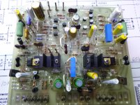
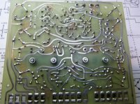
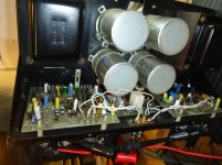
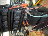
Some pictures of the amp and pcboard, there is no front plate for now, and yes audio wires are to be replaced...
Replaced R19 from 1Mohms to 470Kohms, now DC offset is below the prescribe 10mV from HK Citation 16A manual.
Mostly this pcboard has shifted in specs, until I can obtain a matched pair of drivers Q13-Q12
Some pictures of the amp and pcboard, there is no front plate for now, and yes audio wires are to be replaced...
Attachments
Last edited:


DC offset on speakers posts.
Well to compare both channels now , both varies a bit and changes from below 10mV to 25mV of course I'm having some music on them just to make running and stop terminate inputs and measures, kind of normal I think.
But what fuzz me, it's both VR1 are set to near or at -10Vdc for correcting offset.
I wonder if new or recent amps needs to have such a negative volts correction?
Of course depending on design. but this amp is from 1976 era ....
Thanks for the piccys, it always good to see what is being worked on. They look clean and in good order.
Although the offset correction (-10vdc) sounds a lot, if you think about it you'll see its actually a very tiny correction in the scheme of things. What is important is the current injected into the R16,17,18 node and 1meg and 10 volts gives a current of just 10uA. So its pretty low. It is trying to develop a correction voltage across the combined resistance of R18 and R3.
Although the offset correction (-10vdc) sounds a lot, if you think about it you'll see its actually a very tiny correction in the scheme of things. What is important is the current injected into the R16,17,18 node and 1meg and 10 volts gives a current of just 10uA. So its pretty low. It is trying to develop a correction voltage across the combined resistance of R18 and R3.
Conclusion dc offset HK Citation 16A
Got a new pair of PNP -NPN MPSU10 and MPSU60 transistors.
Replaced Q13 as low hfe readings below his complementary Q12 at 36 instead of 50.
Installed new Q13 MPSU60 transistor in place, and this push dc offset in the positive region. Then installed the Q12 NPN MPSU10 and got a better balance.
Like R19 play a role in compensation of current in the stage for correcting DC offset went from 470Kohms to 330Kohms.
Now I can trim down DC offset to zero and have some play in positive and negative region with VR1.
I did apply the same logic to R19 on the other good pcboard. as this one had the VR1 adjustment pot all the way to -10vdc to properly trim down DC offset.
Installed a 470Kohms and now DC offset is fine to below 10mV, with room for adjusting trimpot VR1.
Now I had a long term test and this HK Citation runs clean and real HiFi
Now summer is here might use it outdoor for backward party!
Many thanks to Mooly for the help
Regards.
 Its definitely been one of the weirder 'issues' I have come across.
- Status
- This old topic is closed. If you want to reopen this topic, contact a moderator using the "Report Post" button.
- Home
- Amplifiers
- Solid State
- HK Citation 16A Dc offset issue