On the lookout for CSA-14 and CSA-28 schematics, repair manuals or other information.
I have a CSA-14 and from what I understand the CSA-28 was made with the same pcb (even says CSA-14 on the silkscreen) but has the added bonus of remote control operation. However, it seems there are some layout differences even though the pcb for both says CSA-14
I was curious if I could retrofit the alps motorized pot on board. Do you think I could squeeze it in? Or another type of motorized pot?
Also I’d like to give it a good, clean bill of health and maybe replace the electrolytics.
It was adapted for 110 from 220V and it looks like some other changes may have been made so I’d like to give it a good once over.
It’s quite a nicely built piece of kit. Apparently the building of these was outsourced to a mil contractor. Very interesting use of LEDs to quickly identify faults. If an LED on the board goes out, you know exactly where to look.
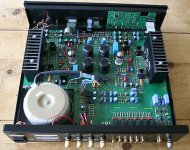
Here’s mine (CSA-14):
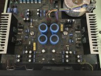
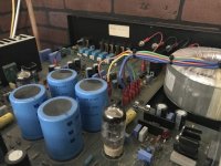
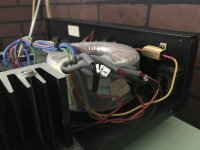
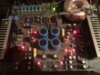
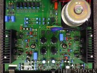
The CSA-28:
Copland and their Canadian distributor were no help and honestly quite grouchy. Seems par for the course for these kind of folks I guess.
I have a CSA-14 and from what I understand the CSA-28 was made with the same pcb (even says CSA-14 on the silkscreen) but has the added bonus of remote control operation. However, it seems there are some layout differences even though the pcb for both says CSA-14
I was curious if I could retrofit the alps motorized pot on board. Do you think I could squeeze it in? Or another type of motorized pot?
Also I’d like to give it a good, clean bill of health and maybe replace the electrolytics.
It was adapted for 110 from 220V and it looks like some other changes may have been made so I’d like to give it a good once over.
It’s quite a nicely built piece of kit. Apparently the building of these was outsourced to a mil contractor. Very interesting use of LEDs to quickly identify faults. If an LED on the board goes out, you know exactly where to look.
Here’s mine (CSA-14):


The CSA-28:


Copland and their Canadian distributor were no help and honestly quite grouchy. Seems par for the course for these kind of folks I guess.
Led5
my model is Copland csa 14, last month the amplifier facing, d12 ( 16v zener ) short, & cause r68 (100 ohm ) burn. after fix up, i try pump in audio signal in, & no output from speaker.
question: All Red Led is on except Led5 ( green Led ). should LED 5 on under healty condition, or it should off, unless have defeact. Pls help
if you look at where the green led is you will have a clue of what is wrong.
it is in the area of the power supply transformer and right next to a relay, which suggests that either your amplifier is in protection mode .
look what you have as voltage upstream of the relay, it cuts your speaker output so if it is open you will not be able to see what you actually have at the speaker output.
and download the service manual to try to understand what you are doing
Last edited:
i need help to fix the csa14-
As the LeD 5 is off. Any glue could provide to diagnos the fault.
1) any correct voltage reference should be at specific part of protection circuit.
2) if the reference voltage at protection cct is abnormal, what should we do .?
3) resistor R182 one end to R83, the othe terminal ( right sensor ) should tie to where ?
4) RL7, connection not very clear. question a) should Relay terminal ( connect to left out),flip to D1 anode when the amplifier is working. ?
thank you & hope to get yr reply asap
simple.
first and to determine if your amp has a problem or if it is the protection circuit that has a problem (which is possible) you must measure the voltages coming from the power transistors (the output voltages speaker) upstream of the relay.
consider your relay as a switch, you have to measure what you have on the relay terminals on the permanent contact side.
from there you will know where to go.
thanks for the glue. further question
RL7, act as switch to connect the speaker ( out ) to the transitor T13, T15. Could i know under nornal working condition, what should be the DC voltage at collector / emitter of T13, T16. ( just a DVM without scope, is it sufficeirnt to do the diagnos )
During the On power troubleshooting , if no speaker are connected to Amplier output , is it ok ? thaks again for yr help
need help for below issue
thanks for the glue. further question
RL7, act as switch to connect the speaker ( out ) to the transitor T13, T15. Could i know under nornal working condition, what should be the DC voltage at collector / emitter of T13, T16. ( just a DVM without scope, is it sufficeirnt to do the diagnos )
During the On power troubleshooting , if no speaker are connected to Amplier output , is it ok ? thaks again for yr help
- Home
- Amplifiers
- Solid State
- Copland CSA-14 and CSA-28 Schematics