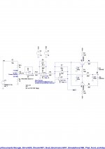
Here is the schematic drawing for my amplifier.
It has only been simulated with LTspice and not built yet because I don't have a practical electronics build bench.
Very good results with simulator.
Amplifier specification:
* For high end audio applications
* Class AB or Class G configurations upto 5000 Watts per channel into 4 Ohms
* PSU rail voltages up to +/- 100 Volts
* High PSU rail ripple voltage reduces electrolytic capacitor physical size
* Lateral power MOSFET (ECW20N20 ECW20P20 )
* Ambient temperature stable design operating from -40'C to +60'C, (outdoor concerts in winter Lapland & summer Death Valley)
* J-Field effect transistor VAS stage
* Phase margin 60 degrees, gain margin 13.5dB
* Phase lag at 20 Khz is less than 2 degrees
* Bandwidth includes a DC response final power stage to > 192 KHz
* Low and stable DC loudspeaker offset voltage
* Very low THD + Noise
* Indefinite short circuit protection simultaneously with a cold MOSFET junction.
* Automatic recovery from short circuit without cycling the power to the amplifier
* No electromechanical relays
Attachments
Last edited:
Anybody built and tested the circuit here? Ibiza Superclub amplifier.
Previously the amplifier was using Jfet LS94, the drain source operating current was around 1mA.
I am now considering changing to a LSJ74C with a drain to source operating current of about 3mA.
Contact me directly for the drawings that shows LLC power supply, D.C offset fault detection, blown mosfet fault detection.
To get this amplifier to work in class G, two LLC power supplies are needed:
1) 240 Volts to +/- 50 Volts at 500 Watts,
2) 240 volts to +/- 100 Volts at 1000 Watts. I tried to do it all with one LLC transformer but gave up and decided to use mature off-the-shelf available parts, two LLC PSU's.
A enable line to the LLC power supply shuts off the LLC power supply's if a power mosfet is detected to blown short circuit, or the loudspeaker load is short or too low.
The LLC power supplies have their grounds connected together.
Another isolated power supply to make +/- 15 Volts at 100mA is also required.
You can make this for hobby use and academic research only, not for commercial use without a royalty payment license to Goat Electronics LTD, lion.palmbeach@gmail.com.
Well, as Bob Pease used to say, in theory there is no difference between theory and practice, but in practice there is. And a lot.
Starting with, +-100V power rails will get you 1.25kW assuming no rail sag or loss, which is a pretty big assumption with lateral MOS. Even in class G at least 4 pairs of MOSFETs will be needed in the amp and in the PSU for 4 ohm operation, double that for 2 ohm operation to get your alleged 5kW (assuming bridge operation into 4 ohms) - and that is if they are selected. If not, a 5th and 6th pair will have to be added for good measure and proper current sharing. The layout of the amplifier will not be simple to say the least.
@suzyj - either way (class G or H) laterals are really not the optimum for the power supply part. Regular HEXFET will do just fine as followers here, with less voltage overhead, in either case the driving circuits need to be able to supply voltages above the main PSU power rails to properly turn on the MOSFETs and avoid losses.
A pro-lateral argument can be had for the actual output stage as it does make thermal management of the output stage simpler and, many will argue laterals sound better and are more robust - but it WILL be expensive.
Other changes include:
1) 4 phase 4 transformer LLC power supply.
2) IXYS digital capacitor in-rush control.
2) Changing the front-end circuit so that soft clipping threshold is related to amplifier rail voltage and varies with generator sag and swell.
Yes, this amplifier is very expensive, but it is the best.
1) 4 phase 4 transformer LLC power supply.
2) IXYS digital capacitor in-rush control.
2) Changing the front-end circuit so that soft clipping threshold is related to amplifier rail voltage and varies with generator sag and swell.
Yes, this amplifier is very expensive, but it is the best.
Hi
What is an LLC supply?
Mosfets rated at >300W require liquid cooling. Look at their SOAR and you see no DC line. Extrapolate downward and you find the "linear" capability of these switching mosfets is very poor.
Rail switching is usually done in a much simpler way using just mosfets and a little bootstrapped "look-ahead" supply that floats on the output. It's been around since at least 1985 and I've used in some high-power amp with multiple rails.
To keep the linear output devices cool, you must have a much lower low-V rail, and ideally use three tiers instead of two. Doing this keeps dissipation quite low compared to a pure linear amp running off only the highest rail.
Having variable rails is also easy and the aforementioned look-ahead circuit does this in simulation and so takes some of the heat.
Using a linear supply, the usual way to configure the PT is as a CTed winding with taps symmetrical about the CT for the lower rails. A bridge across the outer ends; a bridge across the next taps in; a bridge across the innermost taps, with caps typically stacked on the DC outputs. Some protection diodes across the caps to keep reverse voltage low during aberrant discharge. The PT is 1500VA in the largest amps.
Unless you are using an industrial mains supply, you won't be getting more than 1kW of audio power if plugged into a normal home outlet.
Hi
What is an LLC supply?
Just a switch mode power supply - where the output transformer is part of a resonant circuit. At resonance, the voltage and current into the transformer are in phase, and the transistors driving them switch OFF exactly where the waveform naturally crosses through zero. This gets rid of most of the switching loss and runs much more efficiently. They are a bitch to design and build.
The amplifier is a piece of cake by comparison.
Unless you are using an industrial mains supply, you won't be getting more than 1kW of audio power if plugged into a normal home outlet.
Less than 1kW average power for sure. I’m not sure exactly when it was, but at some point in the past they changed the rules for nameplate ratings for amplifiers. Back in the day, AC current consumption was spec’ed on the back for FULL sine wave output power, even if such could not be sustained indefinitely. Now it is spec’ed For 1/8 of full sine power, on average, using pink noise. Make no mistake - such a signal does drive the amp into clipping. But it is a more realistic amount of AC current draw, more in line with how an audio amplifier will be used. If they went back to the old way, you wouldn’t be able to plug a rock concert into a football stadium’s electrical system. there would not be enough ampacity to deal with multiple racks full of Labgruppens if they had to rate their AC draw at full sine wave. The systems they use are megawatts of “audio” power.
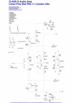
Here is the latest design for a 4000W per channel class G/H amplifier.
Does anybody want to make this amplifier?
The power supply uses a 90 Volt to 260 Volt PFC rectifier followed by flyback transformers.
Hope to get it working for a demo at Notting hill carnival UK.
Front end and short circuit protection as the original post.
Does anybody want to make this amplifier?
The power supply uses a 90 Volt to 260 Volt PFC rectifier followed by flyback transformers.
Hope to get it working for a demo at Notting hill carnival UK.
Front end and short circuit protection as the original post.
Attachments
Here are the power stages, Keep It Simple Stupid! KISS
also, a test sample max power beat from underworld born slippy.
The circuits show the basic concept but some components may need application tweaking.
also, a test sample max power beat from underworld born slippy.
The circuits show the basic concept but some components may need application tweaking.
Attachments
Eight Goats Sound System Rig.
There are eight vertical lines of high-power high-fidelity mid-high & subwoofers connected to a computer running four stereo sound cards (eight channels). Sound from the loudspeakers is non-mixed single point sources; this improves the sound fidelity by orders of magnitude compared to traditional stereo loudspeaker clusters. The soundcard also monitors the amplifier output and automatically generates maximum audio power; this is done by looking at the amplifier output and calculating acceptable distortion and clipping limits.
There are eight vertical lines of high-power high-fidelity mid-high & subwoofers connected to a computer running four stereo sound cards (eight channels). Sound from the loudspeakers is non-mixed single point sources; this improves the sound fidelity by orders of magnitude compared to traditional stereo loudspeaker clusters. The soundcard also monitors the amplifier output and automatically generates maximum audio power; this is done by looking at the amplifier output and calculating acceptable distortion and clipping limits.

If any professional audio engineers wanted to meet me in person to discuss making this amplifier I could visit your stand if you are exhibiting at Plasa 15 - 17 September 2019 | Olympia, London.
It should be Class D in todays time, if somebody interested
I made some improvement changes to the front end to reduce the number of op-amps required.
Also, the soft clipper and anti-saturation circuit now tracks the PSU rail voltage to clip at 25 Volts below rail voltage and is much more consistent with temperature because it works from the amplifier output.
Also, the soft clipper and anti-saturation circuit now tracks the PSU rail voltage to clip at 25 Volts below rail voltage and is much more consistent with temperature because it works from the amplifier output.
Attachments
- Status
- This old topic is closed. If you want to reopen this topic, contact a moderator using the "Report Post" button.
- Home
- Amplifiers
- Solid State
- Electronic circuit for Hi-fi class G