Hi Huggy, My amp has been shelved for some time. Life commitments has stopped all further diy until I get some time. I have other amps to finish also, can’t wait to get stuck back in. Hopefully after Christmas things will settle down. Good luck with finding the problem mate.
Hi Bix
I'm giving up too for now.
I try to understand the diagram but without success, I end up with
a low voltage dc (1.2v) output without understanding why.
I lifted each transistor and diodes on the sick side, all tested, changed a 4793, but nothing works, changed the op circuit DC servo, same ...
he brings me up, so before he goes through the window, I take a break, and leave
on a nice marantz 1030 any first generation (serial n ° 1300)
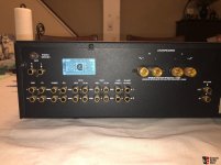
I want to know, how many areas on the main board (PCB) are there, where thermal stress is an issue (many audio components of this brand and several other manufacturers from U.K. don't longer work cause this often to observe problem).
A friend of me purchase two not working devices of this model and want to enhance the long time reliability regarding sound quality and life time.
He is planning an outsourced power supply (outdoor) unit and therefore has a free choice in term to reducing the supply voltages and possibly increasing the quiescent currents in the input, VAS and output stages to improve the sonic character (output power should be reduced to a quarter this means undistorted SPL = -6db in opposite to the genuine condition).
Maybe one of the users of this integrated amplifier can create images of the main board (top view) with a thermographic resp. an infrared camera while operating - thank you very much.
Some URLs:
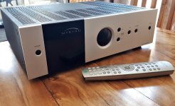
Product Review
Myryad-MI-240
Myryad Mi | Product overview | What Hi-Fi?
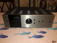
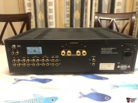
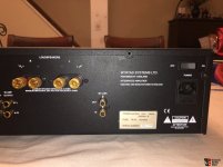
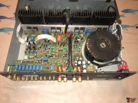
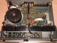
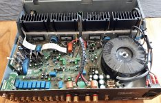
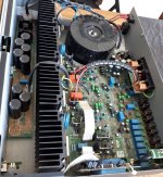
Some images from inside I have found by chance on the web:
A friend of me purchase two not working devices of this model and want to enhance the long time reliability regarding sound quality and life time.
He is planning an outsourced power supply (outdoor) unit and therefore has a free choice in term to reducing the supply voltages and possibly increasing the quiescent currents in the input, VAS and output stages to improve the sonic character (output power should be reduced to a quarter this means undistorted SPL = -6db in opposite to the genuine condition).
Maybe one of the users of this integrated amplifier can create images of the main board (top view) with a thermographic resp. an infrared camera while operating - thank you very much.
Some URLs:
Product Review
Myryad-MI-240
Myryad Mi | Product overview | What Hi-Fi?
Some images from inside I have found by chance on the web:
Attachments
-
 2950682-af8555d1-myryad-mi-240-ss-integrated-amplifier.jpg92.5 KB · Views: 310
 -
 2950687-6bf24aae-myryad-mi-240-ss-integrated-amplifier.jpg103.5 KB · Views: 242
 -
 2950684-5138a9c1-myryad-mi-240-ss-integrated-amplifier.jpg140.1 KB · Views: 188
 -
 2950683-28f2ef59-myryad-mi-240-ss-integrated-amplifier.jpg131.8 KB · Views: 286
 -
 2950686-49fbb5f7-myryad-mi-240-ss-integrated-amplifier.jpg156.4 KB · Views: 265
 -
 2950685-db52796f-myryad-mi-240-ss-integrated-amplifier.jpg177.8 KB · Views: 261
 -
 e01a5e314d0482d0461553e5b6a3.jpg209.5 KB · Views: 284
 -
 3df9a9b1444fb63155b4d75c5010.jpg331.7 KB · Views: 358
 -
 cc08e32545d4806611da7f19393e.jpg413.2 KB · Views: 254
Last edited:
it's been a long time since I gave up and recycled it but what I can say and the main problem with myriad is that part of the circuit always remains live even when the device is turned off which causes it to cook literally over a low heat.
now when i see a myriad amp, i run away!
good luck
now when i see a myriad amp, i run away!
good luck
Thanks for the pointers here on this model and for the manual link. I've been working on an MA360.. the 3 channel version of the MA240. This was silent on all 3 channels. The relays were not tripping in, but nothing was apparently blown.
I post my findings here as it is a slightly unusual component to fail in this position and should help others arriving here as one of the earlier posts sounds to have had the same symptoms and I daresay it could be a circuit weakness/ common issue.
The amp has some switched +60v and -60v regulator rails. (Q503/Q505 for the + and Q504/Q506 for the -) The -60v was missing although the main -60v was being supplied to the switching transistors.
The actual issue turned out to be 2 47Kohm resistors R506 and R507 in the switching line that the STBY line lifts to turn on. one was O/c , the other read 87Kohms. The positive rail was switching, but no current through R507 so no negative rail. All 3 channels cut in and work once these 2 resistors had been changed.
Andy

Dear Andy,
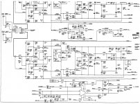
I've got a MA500 five channel power amplifier that has a problem, apparently on th epower supply. There is a resistor (I think a fuse resistor) that burns after some hours. One time also a two transistors burned. I can't find out the root cause. The problem appears on the +60V power rail. I don't have the schematics of the amplifier, but I drew it following the traces on the PCB and the schematics of the MA240 / MA360 that in some parts are similar.

In the diagram the resistor that burns is R609. Currently the output on +/-60V rails is 59,7 on the +60 rail and 59 on the -60 rail. After pwer up, Q601 and Q602 are very hot, but normally they workerd hot (I don't know how much) because the area in which they are has always been the hottest as you put a hand over the cover of the amplifier.
I would greatly appreciate if you or someone else could help me!
By the way: does anybody own the service manual of gthe MA500?
I've got a MA500 five channel power amplifier that has a problem, apparently on th epower supply. There is a resistor (I think a fuse resistor) that burns after some hours. One time also a two transistors burned. I can't find out the root cause. The problem appears on the +60V power rail. I don't have the schematics of the amplifier, but I drew it following the traces on the PCB and the schematics of the MA240 / MA360 that in some parts are similar.
In the diagram the resistor that burns is R609. Currently the output on +/-60V rails is 59,7 on the +60 rail and 59 on the -60 rail. After pwer up, Q601 and Q602 are very hot, but normally they workerd hot (I don't know how much) because the area in which they are has always been the hottest as you put a hand over the cover of the amplifier.
I would greatly appreciate if you or someone else could help me!
By the way: does anybody own the service manual of gthe MA500?
The vlotage supply for the pre-drive of the power amp and current consumption is not great. The problem is the voltage on pins C,E of Q601 and Q602 too high, so that when they are working their dissipated power are very high and hot. The resistor R609 and R612 both resistance should be increased to have more voltage drop to share the Q601 and Q602 power dissipation (47 ohm is low). How to do that try increasing both R609 and R612 resistance, use a suitable watt resistor, monitoring the output voltages which can not drop and checking the transistors for lower temp.
Thank you very much for ypour reply!The vlotage supply for the pre-drive of the power amp and current consumption is not great. The problem is the voltage on pins C,E of Q601 and Q602 too high, so that when they are working their dissipated power are very high and hot. The resistor R609 and R612 both resistance should be increased to have more voltage drop to share the Q601 and Q602 power dissipation (47 ohm is low). How to do that try increasing both R609 and R612 resistance, use a suitable watt resistor, monitoring the output voltages which can not drop and checking the transistors for lower temp.
The first time the amplifier faulted, R609 and R604 burnt and R603 overheated (but was still good):
In a first attempt to repair the amplifier, I changed R609 and R604 with 1W resistors, copying the values from R606 and R612 as R04 and R609 were too damaged to read or measure the values. The result was the burning of some transistors (I don't remember which), or perhaps they were already damaged (I didn't check before changing the resistors) and for this the resistors burnt...
The problem was that (as I desume from MA240 shematics) R609 and R604 are fuse resistors that protect the downstream components.
R609 is 0,5 W to preserve Q601, as this is about the maximum power that Q601 can dissipate with its heater. I think that this was the idea of the original design, even if it causes some components to become hot (R609, Q601).
If we increase the power of the resistors, I fear that the downstream components could be damaged in case of problems. And indeed here we have a problem somewhere.
Do you think that it is a problem having +59,7 and -59 instead of +60 and -60? What could happen to the downstream channells amps? I don't know if before the repair the voltages were correct...
This is part of the audio channels schematics (taken form the circuit and looking at the MA240 schematics):
Any advice is wellcome!
If both channel pre-drive circuit of the power amp are ok, the supply voltage +59,7 and -59 instead of +60 and -60 should be no problem. About fuse resistors, you can use the original 0,5 W resistor and adding another bigger value resistor in series for that propose no problem. The supply circuit double the input voltage and regulated to + -60V output, there are high voltage drop on the output transistors and the result is high temp. You can try to test and not every amp design is perfect.
Your are right: I can try with a 100 ohm 2W resistor in series with R609 (and one in series with R612). This 100 ohm resistor should dissipate about 1 W at most and this will be subtracted to the power that Q601 and Q602 have to dissipate. This should keep them a little bit cooler.If both channel pre-drive circuit of the power amp are ok, the supply voltage +59,7 and -59 instead of +60 and -60 should be no problem. About fuse resistors, you can use the original 0,5 W resistor and adding another bigger value resistor in series for that propose no problem. The supply circuit double the input voltage and regulated to + -60V output, there are high voltage drop on the output transistors and the result is high temp. You can try to test and not every amp design is perfect.
I will take me some time to find the resistors and to install them. I will be back once the test is done.
Thank so much for the suggestion.
I've received the 100 ohm / 2W resistors and installed them. The trick seems to work, but the resistors get very hot, especially the one on the +60V line. Measured with a multimeter the current on the resistance seems only slightly bigger that that on the -60V line (I measure the voltage drop across the resistor). But I had a big surprise changing the measurement from DC to AC: with two channels installed the DC measurement is about 4V but the AC measure ai about 10V! The same is not true on the -60V line where I get 3.75V DC and 0.025V AC. So I connected an oscilloscope to the output of R609 (Q601 & Q603 collector) and saw that there is a periodic drop af about 40V (with three channels, about 23 with two channels) in the voltage at Q601 collector. This increases the current and the power dissipated by the resistirs and the transistors. Now my question is: is this normal? Why the -60V line has not he same behavior?If both channel pre-drive circuit of the power amp are ok, the supply voltage +59,7 and -59 instead of +60 and -60 should be no problem. About fuse resistors, you can use the original 0,5 W resistor and adding another bigger value resistor in series for that propose no problem. The supply circuit double the input voltage and regulated to + -60V output, there are high voltage drop on the output transistors and the result is high temp. You can try to test and not every amp design is perfect.
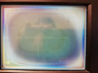
In the attache image (is very bad because the oscilloscope is old and with a broken display) there is the voltage drop across the 100 ohm resistor with three channels connected: from the oscillograms the base voltage is about 2 volts with peaks of about 30V every 6/7 us.
What should I investigate to find where the problem could be?
Attachments
Thank you for your reply and suggestion. I will follow your advice.
In the mean time I managed to get a better scope. Here are some pictures.
048 is the voltage across the 100 ohm resistor placed downstream R609 with only one channel installed.
The oscillogram is more or less the same with each one of the channels, so I think that the problem is not in one of the channels powered by in the power supply itself.
055 is taken across R604 with only one channel driven.
057 is taken at the output of R606 (AC coupling) because I'm not able to measure across it (noo room to fix the probe ground).
They are quite different (note the vertical scale is x10).
I will check the capacitors that you indicate.
- Home
- Amplifiers
- Solid State
- Myryad MA 240 service manual