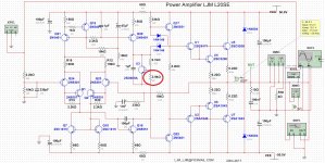
First modification - Setting BIAS
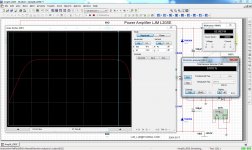
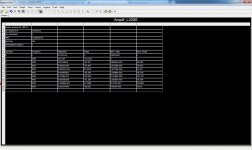
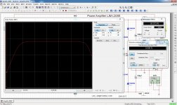
Circuit, response and fourier curve.
Resistance switch from 4.7k to 3.9k
Bending on the response curve. Attenuated peaks at the higher frequencies and amplified range of high frequencies at the amplification. It allows greater amount of harmonics.
Circuit, response and fourier curve.
Resistance switch from 4.7k to 3.9k
Bending on the response curve. Attenuated peaks at the higher frequencies and amplified range of high frequencies at the amplification. It allows greater amount of harmonics.
Attachments
Last edited:
or...
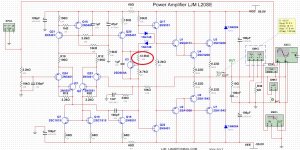
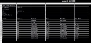
Circuit, response and fourier curve.
Resistance switch from 9.1k to 12.0k - THD 0.009
Bending on the response curve. Attenuated peaks at the higher frequencies and amplified range of high frequencies at the amplification. It allows greater amount of harmonics.
Circuit, response and fourier curve.
Resistance switch from 9.1k to 12.0k - THD 0.009
Bending on the response curve. Attenuated peaks at the higher frequencies and amplified range of high frequencies at the amplification. It allows greater amount of harmonics.
Attachments
Last edited:
Circuit, response and fourier curve.
Resistance switch from 9.1k to 12.0k - THD 0.009
Bending on the response curve. Attenuated peaks at the higher frequencies and amplified range of high frequencies at the amplification. It allows greater amount of harmonics.
ATTENTION! These last two changes did not really work out. caused overload and burnout of the fuse.
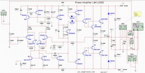
Circuit, response and fourier curve.
Resistance switch from 4.7k to 3.9k
Bending on the response curve. Attenuated peaks at the higher frequencies and amplified range of high frequencies at the amplification. It allows greater amount of harmonics.
ATTENTION! These last two changes did not really work out. caused overload and burnout of the fuse.
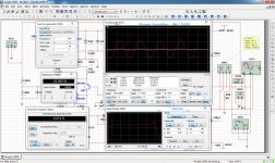
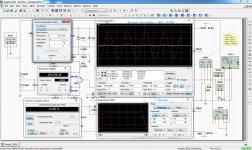
Second change - Change in gain and output power
Signal source: 1khz 1v sinusoidal
Source of +50 0 -50v DC
Changed differential input gain resistors - 10k to 15k.
Power Consumption - 2.05A to 3.24A
Output power - 82W to 204w
THD - 0.012% to 0.026%
Per channel
Signal source: 1khz 1v sinusoidal
Source of +50 0 -50v DC
Changed differential input gain resistors - 10k to 15k.
Power Consumption - 2.05A to 3.24A
Output power - 82W to 204w
THD - 0.012% to 0.026%
Per channel
Attachments
Last edited:
Hello Eliseu! Can i use a voltage supply of + - 54V? do i have to change any resistor?
where i can find the best kit available to buy? Thank you very much
Olá!
A tensão que esse projeto suporta está entre +-15 VDC a +-65 VDC. Não precisa alterar nenhum resistor nessa faixa de tensão.
Recomendado +-40 VDC
Corrente de 4A por canal
Este kit eu comprei no Aliexpress
Hello!
The voltage that this design supports is between + -15 VDC to + -65 VDC. You do not need to change any resistors in this voltage range.
Recommended + -40 VDC
4A current per channel
This kit I bought on Aliexpress
Last edited:
Hello Eliseu! Can i use a voltage supply of + - 54V? do i have to change any resistor?
where i can find the best kit available to buy? Thank you very much
Este kit eu comprei no Aliexpress. Não é o melhor nem o pior. Vai depender do que você procura. Mais potência, maior qualidade, menos distorção...
This kit I bought on Aliexpress. It is not the best nor the worst. It will depend on what you are looking for. More power, higher quality, less distortion ...
Obrigado pela rápida resposta! É que eu queria usar um transformador retirado de um amplificador Technics que depois da filtragem tem cerca de + - 54dc
Thanks for the quick response! Is that I wanted to use a transformer taken from a Technics amplifier that after filtering has about + - 54dc
Thanks for the quick response! Is that I wanted to use a transformer taken from a Technics amplifier that after filtering has about + - 54dc
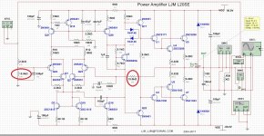
I have the same experience as Eliseu, change of bias from 15mA/transistor to a higher value (I have tried 200mA) causes instability, with a voltage of +/-40V.
I therefore do not recommend changing the 9,1k and 4,7k resistors.
The bias of 15mA is really low, I have another amplifier kit from this chinese designer, a NAP250 mod, and it seem to be stable with a nice bias of 500mA/transistor. I will post a review when I have finished testing it.
I therefore do not recommend changing the 9,1k and 4,7k resistors.
The bias of 15mA is really low, I have another amplifier kit from this chinese designer, a NAP250 mod, and it seem to be stable with a nice bias of 500mA/transistor. I will post a review when I have finished testing it.
I have the same experience as Eliseu, change of bias from 15mA/transistor to a higher value (I have tried 200mA) causes instability, with a voltage of +/-40V.
I therefore do not recommend changing the 9,1k and 4,7k resistors.
The bias of 15mA is really low, I have another amplifier kit from this chinese designer, a NAP250 mod, and it seem to be stable with a nice bias of 500mA/transistor. I will post a review when I have finished testing it.
")

Hi Eliseu,Este kit eu comprei no Aliexpress. Não é o melhor nem o pior. Vai depender do que você procura. Mais potência, maior qualidade, menos distorção...
This kit I bought on Aliexpress. It is not the best nor the worst. It will depend on what you are looking for. More power, higher quality, less distortion ...
I'm a newbie in this audio hobby.
Few questions for you to enlighten my audio spirit
- Is this a good amp regarding sound quality? Do you recommend any other amps? If so, can you post the links?
- Are you using this LJM L20SE board with the components that came with it or do you recommend any modification? Any addition to this amp besides a power supply?
- Why is +/- 40VDC recommended? Is there issue (degradation of sound, etc) from +/- 40VDC to +/- 60VDC?
- What do you recommend as power supply (transformer and rectifier)? Can you send links to where I can buy those?
PS: I'm interested in this L20SE amp due to its power capability but I also want sound quality. I would like an amp with at least 150W per channel (ideally 200W) to drive a 4ohm speaker. Please recommend other amp if you think there's a better choice.
Thank you for the time replying to my newbie questions. Valeu!
Hi Eliseu,
I'm a newbie in this audio hobby.
Few questions for you to enlighten my audio spirit
- Is this a good amp regarding sound quality? Do you recommend any other amps? If so, can you post the links?
- Are you using this LJM L20SE board with the components that came with it or do you recommend any modification? Any addition to this amp besides a power supply?
- Why is +/- 40VDC recommended? Is there issue (degradation of sound, etc) from +/- 40VDC to +/- 60VDC?
- What do you recommend as power supply (transformer and rectifier)? Can you send links to where I can buy those?
PS: I'm interested in this L20SE amp due to its power capability but I also want sound quality. I would like an amp with at least 150W per channel (ideally 200W) to drive a 4ohm speaker. Please recommend other amp if you think there's a better choice.
Thank you for the time replying to my newbie questions. Valeu!
Hi JPMA,
I asked these same questions at the beginning of my hobby of assembling amplifiers. But the answers were not always as expected.
For years I have done a lot of reading on the subject. Some things I learned from the experience. Projects that worked, went wrong, or never finished.
- In its original design, the L20SE is a good amplifier for home use. 80W RMS at 4 ohms (this is the actual power of it) and 0.011% THD (Input pattern with a 1 Khz sine wave and 1 VAC). High-fidelity amplifiers have THD less than 0.5%.
- I'm using two LJM L20SE boards doing minor modifications and testing as I show here.
- This design supports +/- 15 to +/- 65 VDC. +/- 40 VDC is recommended. Using +/- 60 VDC causes a bit more source noise, riple (AC frequency of 50 or 60 Hz) and does not increase power. What really matters is the transformer current, 8 A per channel at least (well defined bass).
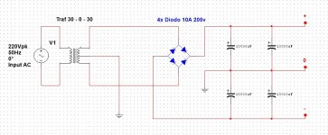
- 1x Toroidal transformer +/- 28-32 VAC, 16-20 A. 4x Diodes 10 A, 200 V minimum. 4X Electrolytic capacitor 10,000 uF, 50V minimum. 8x Capacitor polyester or ceramic 100 nF, 100v minimum (optional). 2x artezanal confection filter (optional).
Note 1. In order to have an auditory perception that a 100 W RMS amplifier has doubled its power it is necessary to increase the power 4 times more, that is 400 W RMS.
Note 2. Normally, a larger power amplifier has more source noise. A higher current rectifier bridge and a higher voltage transformer generate more ripple. The higher the power, the more or more capacitor values will be needed.
Note 3. No links to purchase. I bought, I mounted, I put the link of the product, but I do not indicate sellers. Every purchase is a negotiation.
Note 4. The journey is long. If you have the skill and curiosity to eat for small projects and then go ahead.
-------------------------------------
Eu fiz estas mesmas perguntas no inicio de meu hobbie de montagem de amplificadores. Mas nem sempre as respostas foram as esperadas.
Durante anos fiz muita leitura sobre o assunto. Algumas coisas aprendi com a experiência. Projetos que deram certo, que deram errado ou que nunca conclui.
- Em seu projeto original, o L20SE é um bom amplificador para uso doméstico. 80W RMS em 4 ohms (esta é a potência real dele) e THD 0.011% (Teste padrão na entrada com uma onda senoidal 1 Khz e 1 VAC). Amplificadores de alta fidelidade tem THD menor que 0.5%.
- Estou usando duas placas LJM L20SE fazendo pequenas modificações e testando conforme mostro aqui.
- Este projeto suporta de +/- 15 a +/- 65 VDC. +/- 40 VDC é o recomendado. Itilizar +/- 60 VDC causa um pouco mais de ruído da fonte, riple (frequência AC de 50 ou 60 Hz) e não aumenta a potência. O que importa mesmo é a corrente do transformador, 8 A por canal no mínimo (graves bem definidos).
- 1x Transfomador toroidal +/- 28-32 VAC, 16-20 A. 4x Diodos 10 A, 200 V mínimo. 4X Capacitor eletrolítico 10.000 uF, 50 V mínimo. 8x Capacitor poliéster ou cerâmico 100 nF, 100v mínimo (opcional). 2x filtro confecção artezanal (opcional).
Obs 1. Para se ter uma percepção auditiva de que um amplificador de 100 W RMS dobrou de potência é necessario aumentar a potência 4 vezes mais, ou seja 400 W RMS.
Obs 2. Normalmente, um amplificador de potência maior, tem mais ruído da fonte. Uma ponte retificadora de maior corrente e um transformador de maior tenção gera mais riple. Quando maior a potência mais ou maiores valores de capacitores serão necessarios.
Obs 3. Sem links para compra. Comprei, montei, coloquei o link do produto, mas não indico vendedores. Cada compra é uma negociação.
Obs 4. A jornada é longa. Se você tem habilidade e curiosidade comesse por pequenos projetos e depois vá avançando.
Last edited:
Eliseu, terminou de montar o seu amplificador?
Gostaria de saber a sua opinião sobre a qualidade do audio.
 Gu62 this is an english speaking forum. If you post native language please also post a translation.
Gostaria de saber a sua opinião sobre a qualidade do audio.
Eliseu, have you finished setting up your amplifier?
I would like to know your opinion on the audio quality.
Gu62 this is an english speaking forum. If you post native language please also post a translation. Gu62 este é um fórum em inglês. Se você postar a língua nativa, por favor, publique uma tradução.
Last edited by a moderator:
Eliseu, terminou de montar o seu amplificador?
Gostaria de saber a sua opinião sobre a qualidade do audio.
Olá! O projeto é bom e a qualidade é boa. É um amplificador HI END.
Hello! The design is good and the quality is good. It is a HI END amplifier.
Hello Eliseu! Can i use a voltage supply of + - 54V? do i have to change any resistor?
where i can find the best kit available to buy? Thank you very much
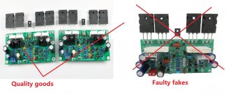
In addition, you need to pay attention to the real goods. And fake goods.
In case of fakes. Please email me LJM_LJM@foxmail.com[/email]
Attachments
I have the same experience as Eliseu, change of bias from 15mA/transistor to a higher value (I have tried 200mA) causes instability, with a voltage of +/-40V.
I therefore do not recommend changing the 9,1k and 4,7k resistors.
The bias of 15mA is really low, I have another amplifier kit from this chinese designer, a NAP250 mod, and it seem to be stable with a nice bias of 500mA/transistor. I will post a review when I have finished testing it.
I think this, and the previous post about the smoked resistor indicates oscillation problems with the amp. If increasing the Iq makes it oscillate, I suspect that it could oscillate when driving a load too, when current increases.
You could try to feed it for example 20kHz square wave, vary the amplitude, and load resistor, and see what the flanks look like on a scope. The LP capacitor on the input should be disconnected for this, and best to disconnect the zobel on the output too.
If it's very prone to oscillate, feeding a sine wave, and watching the output on a scope could reveal a 'thick' or 'blurred' line on the peaks of the sine wave where current is higher. Transistor temperatures can also influence this, so it should be tested cold and 'hot'.
- Home
- Amplifiers
- Solid State
- Power Amplifier LJM L20SE